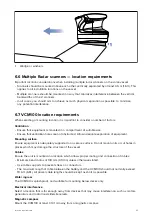
• Mount the scanner above head height out of range of personnel, to avoid mechanical danger and
minimize exposure to electromagnetic radiation.
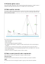
• Radar operates at the line-of-sight, so a high mounting position gives better long range
performance.
• Surrounding large objects, in the same horizontal plane, can interfere with the radar signal and
cause blind areas or shadow sectors and false targets on the radar display (see below).
Do not mount the radar scanner so high that it is affected by the pitching and rolling of the vessel.
Shadow areas and false echoes
Mount the radar scanner away from large structures or equipment, such as engine stacks,
searchlights, horns, or masts. These objects may cause shadow areas and false echoes. For
example, if you mount the radar scanner on a mast, echoes from other targets may be reflected from
the mast. Wet sails may also cause shadow areas, so radar performance may be reduced in the
rain. It is particularly important to avoid shadow areas near the bow. Raising or even lowering the
radar scanner may help to reduce these effects.
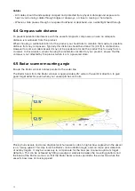
In shadow areas beyond the obstruction there will be a reduction of the beam intensity. There may
be a blind sector if the beam intensity is not sufficient to obtain an echo from an object. This may
occur even at close range. For this reason the angular width and relative bearing of any shadow area
must be determined at installation.
You may be able to detect shadow areas or false echoes on your multifunction display. For example,
sea clutter can be used as a good indicator of blind arcs. Dark sectors on the radar display indicate
possible shadowed areas. This information should be posted near the display unit and operators
must be alert for targets in these blind areas.
Access
The radar scanner should be easily accessible to allow maintenance to be carried out safely.
Sufficient clearance must be allowed to fully open the scanner unit for maintenance and service.
Mounting platform
The radar scanner must be mounted on a rigid and stable platform. The platform must be capable of
supporting the mass and inertia of the radar scanner under seagoing conditions. The platform should
not twist (causing bearing errors) or be subject to excessive vibration or shock.
The platform must be free-draining, to prevent the pooling of water beneath the radar scanner.
The mounting site must be clear of the following:
• Ropes.
• Standing rigging.
• Running rigging.
• Heat.
• Fumes.
• People.
Magnetic compass
Mount the radar scanner at least 1 m away from a magnetic compass.
Multiple radar scanners
If two radar scanners are installed at different locations in a dual radar system, care should be
taken to allow for the difference in position of the radars when switching between the two on your
multifunction display. This is especially noticeable at short ranges on larger vessels.
To reduce possible interference between radar scanners in a dual radar system:
• Maximise the spacing between the scanners.
• If possible, locate the scanners so that they are aligned vertically, one directly above the other,
with a minimum of 2 metres vertical separation.
• If the scanners can’t be aligned one directly above the other, locate each scanner the same
distance from the bow your vessel. Interference is more likely if the scanners are installed one in
front of the other, even when separated vertically.
33
Содержание CYCLONE
Страница 2: ......
Страница 4: ......
Страница 8: ...8...
Страница 15: ...Chapter 2 Document information Chapter contents 2 1 Document information on page 16 Document information 15...
Страница 20: ...20...
Страница 28: ...28...
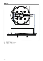
Страница 40: ...Rear exit 1 Mounting surface 2 Power and RayNet connectors 3 Power and RayNet cables 40...
Страница 42: ...42...
Страница 52: ...52...
Страница 53: ...Chapter 9 System connections Chapter contents 9 1 Typical system examples on page 54 System connections 53...
Страница 58: ...58...
Страница 59: ...Chapter 10 Power connections Chapter contents 10 1 Radar power connections on page 60 Power connections 59...
Страница 64: ...64...
Страница 69: ...Chapter 12 Operation Chapter contents 12 1 Operation instructions on page 70 Operation 69...
Страница 80: ...80...
Страница 84: ...84...
Страница 88: ......
Страница 91: ......


