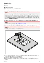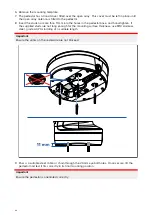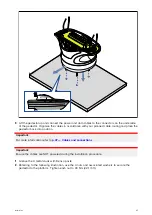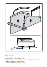
Cables
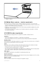
• All cables should be adequately clamped and protected from physical damage and exposure to
heat. Avoid running cables through bilges or doorways, or close to moving or hot objects.
• Where a cable passes through an exposed bulkhead or deckhead, use a watertight feed-through.
6.4 Compass safe distance
To prevent potential interference with the vessel's magnetic compasses, ensure an adequate
distance is maintained from the product.
When choosing a suitable location for the product you should aim to maintain the maximum possible
distance from any compasses. Typically this distance should be at least 1 m (3.3 ft) in all directions.
However for some smaller vessels it may not be possible to locate the product this far away from a
compass. In this situation, when choosing the installation location for your product, ensure that the
compass is not affected by the product when it is in a powered state.
6.5 Radar scanner mounting angle
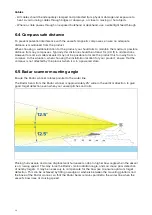
Ensure the Radar scanner rotates parallel to the water line.
The Radar beam from the Radar scanner is approximately 25° wide in the vertical direction, to give
good target detection even when your vessel pitches and rolls.
Planing hull vessels, and some displacement hull vessels, adopt a higher bow angle when the vessel
is at cruising speed. This may raise the Radar’s main radiation angle, and can cause poor detection
of nearby targets. It may be necessary to compensate for the bow rise to ensure optimum target
detection. This can be achieved by fitting a wedge or washers between the mounting platform and
the base of the Radar scanner, so that the Radar beam remains parallel to the water line when the
vessel's bow rises at cruising speed.
34
Содержание CYCLONE
Страница 2: ......
Страница 4: ......
Страница 8: ...8...
Страница 15: ...Chapter 2 Document information Chapter contents 2 1 Document information on page 16 Document information 15...
Страница 20: ...20...
Страница 28: ...28...
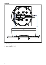
Страница 40: ...Rear exit 1 Mounting surface 2 Power and RayNet connectors 3 Power and RayNet cables 40...
Страница 42: ...42...
Страница 52: ...52...
Страница 53: ...Chapter 9 System connections Chapter contents 9 1 Typical system examples on page 54 System connections 53...
Страница 58: ...58...
Страница 59: ...Chapter 10 Power connections Chapter contents 10 1 Radar power connections on page 60 Power connections 59...
Страница 64: ...64...
Страница 69: ...Chapter 12 Operation Chapter contents 12 1 Operation instructions on page 70 Operation 69...
Страница 80: ...80...
Страница 84: ...84...
Страница 88: ......
Страница 91: ......


