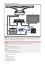
Note:
The maximum length for the radar power cable (including all extensions) is 25 m (82 ft).
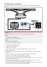
• The radar scanner must be connected to the POWER OUT terminals of the VCM100.
• The screen (drain) strands of the radar scanner's power cable must be connected to one of the
VCM100 SCREEN terminals.
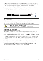
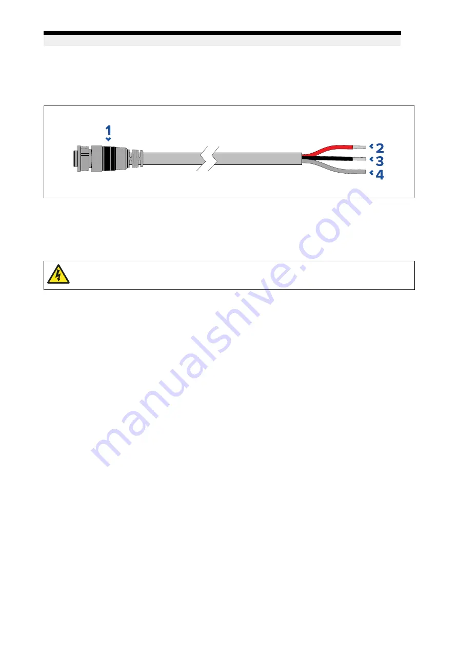
The following diagram illustrates the power connections of the supplied power cable.
1.
Power connector
2. Red wire — connect to the positive POWER OUT terminal of the VCM100.
3.
Black wire — connect to the negative POWER OUT terminal of the VCM100.
4.
Screen (drain) strands — connect to one of the SCREEN terminals of the VCM100.
Warning: Positive ground systems
Do not connect this unit to a system which has positive grounding.
VCM100 power connections
VCM100 power and grounding requirements.
The VCM100 is intended for use on ships’ DC power systems operating from 12 to 24 Volts DC.
• The VCM100 must be connected to a battery isolator switch, or a DC distribution panel.
• The battery isolator switch or DC distribution panel must be connected to the POWER IN terminals
of the VCM100.
• Do NOT connect additional power switches to the cable providing the power feed to the VCM100.
• All power connections between the VCM100 and the power source must have appropriate fuse
protection.
• All power connections must be of high quality to minimize resistance and to remove the risk
of accidental shorts.
• The VCM100 SCREEN terminals must be connected to your vessel's RF ground system.
• Do NOT connect the radar scanner or the VCM100 to a positively-grounded power system.
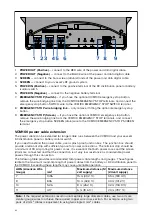
The following diagram illustrates the power connections of the VCM100.
61
Содержание CYCLONE
Страница 2: ......
Страница 4: ......
Страница 8: ...8...
Страница 15: ...Chapter 2 Document information Chapter contents 2 1 Document information on page 16 Document information 15...
Страница 20: ...20...
Страница 28: ...28...
Страница 40: ...Rear exit 1 Mounting surface 2 Power and RayNet connectors 3 Power and RayNet cables 40...
Страница 42: ...42...
Страница 52: ...52...
Страница 53: ...Chapter 9 System connections Chapter contents 9 1 Typical system examples on page 54 System connections 53...
Страница 58: ...58...
Страница 59: ...Chapter 10 Power connections Chapter contents 10 1 Radar power connections on page 60 Power connections 59...
Страница 64: ...64...
Страница 69: ...Chapter 12 Operation Chapter contents 12 1 Operation instructions on page 70 Operation 69...
Страница 80: ...80...
Страница 84: ...84...
Страница 88: ......
Страница 91: ......

