8.1 Warnings and cautions
Important:
Before proceeding, ensure that you have read and understood the warnings and
cautions provided in the
section of this document.
8.2 Schematic diagram
A schematic diagram is an essential part of planning any installation. It is also useful for any future
additions or maintenance of the system. The diagram should include:
• Location of all components.
• Connectors, cable types, routes and lengths.
8.3 Tools required
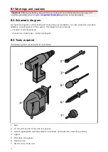
The following tools are required for installation.
1.
Drill
2. 13 mm (0.5 in) and 17 mm (0.6 in) spanner
3.
Drill bit (appropriate size dependent on thickness and material of mounting surface)
4.
Jigsaw
5. Pozi-drive screwdriver
6. Denso paste
7.
50 mm (2 in.) Hole saw
44
Содержание CYCLONE
Страница 2: ......
Страница 4: ......
Страница 8: ...8...
Страница 15: ...Chapter 2 Document information Chapter contents 2 1 Document information on page 16 Document information 15...
Страница 20: ...20...
Страница 28: ...28...
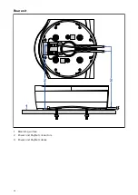
Страница 40: ...Rear exit 1 Mounting surface 2 Power and RayNet connectors 3 Power and RayNet cables 40...
Страница 42: ...42...
Страница 52: ...52...
Страница 53: ...Chapter 9 System connections Chapter contents 9 1 Typical system examples on page 54 System connections 53...
Страница 58: ...58...
Страница 59: ...Chapter 10 Power connections Chapter contents 10 1 Radar power connections on page 60 Power connections 59...
Страница 64: ...64...
Страница 69: ...Chapter 12 Operation Chapter contents 12 1 Operation instructions on page 70 Operation 69...
Страница 80: ...80...
Страница 84: ...84...
Страница 88: ......
Страница 91: ......

