0049-2702-XXX Alliance Series Modems – USER MANUAL
08/05/2010
Rev. A
Page 175 of 197
(dial line options, EIA interface options, etc.). Each digit within the number string represents an
option, and the specific value of each digit (0, 1, E, etc.) indicates the
current option setting
.
On the following pages are diagrams that show –
•
Which options are included in each option group
•
Which option is indicated by each digit within the group
•
The possible settings for each option
To change an option setting
, use the front panel pushbuttons to change the value of the digit
that corresponds to the option you want to change, as explained in the following section.
Summary Setup Pushbutton Functions
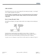
The LCD can display only a portion of the Summary Setup number strings (options) and user
profiles; however, you can scroll across the string of numbers to view the entire display.
For the
Summary Setup and user profile screens only, the front panel pushbuttons function as
follows:
•
Pushbutton 1 moves the cursor to the left. Pushbutton 3 moves the cursor to the right. If
the cursor is at the end of the screen, the screen will scroll one character at a time.
•
Pushbutton 2 changes the flashing value (i.e., the current option setting). When you press
pushbutton 2, the LCD cycles through the possible values (settings).
•
The right arrow button moves the screen to the beginning of the next group of options to
the right. The left arrow button moves the screen to the beginning of the next group of
options to the left. Groups of options are separated by blank spaces on the LCD.
Note:
On the user profile screens (for AT profiles 0 and 1) the cursor location is
indicated by a solid black box when the cursor is positioned in a blank cell (one with no
characters).
Explanation of Summary Setup Screens
Note that options are identified on the Summary Setup screens only by the relative positions of
the digits within the number string, as indicated in the following diagrams. Each digit represents
an option, and the value of each digit (0, 1, E, etc.) indicates the current option setting.
The string of numbers in each diagram shows the factory default setting for each option
(i.e.,
the Hayes mode default settings). Each diagram also identifies all possible settings (values) for
each option.
Note:
Numbers within an option group that are not identified in the following diagrams are
reserved for future use or factory use.
Do not change these numbers
.
Содержание Alliance V.32
Страница 182: ...0049 2702 XXX Alliance Series Modems USER MANUAL 08 05 2010 Rev A Page 178 of 197 ...
Страница 185: ...0049 2702 XXX Alliance Series Modems USER MANUAL 08 05 2010 Rev A Page 181 of 197 ...
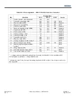
Страница 189: ...0049 2702 XXX Alliance Series Modems USER MANUAL 08 05 2010 Rev A Page 185 of 197 Figure D 1 Connector pin assignments ...


