0049-2702-XXX Alliance Series Modems – USER MANUAL
08/05/2010
Rev. A
Page 82 of 197
The following conditions are required for Leased Line Auto-Recovery:
•
Leased Line Auto-Recovery must be enabled (using the Leased Line Auto-Recovery
Select option) on both communicating modems.
•
The Leased Line Auto-Recovery Select, Return and Test options must be set correctly on
both communicating modems, as explained in the following sections.
•
A dial backup line (or lines) must be installed.
•
The phone number to be dialed (the backup line) must be stored in the originate modem.
The phone number that will be used for Leased Line Auto-Recovery is the number
stored in the phone cell currently displayed in the AUTO-DIAL screen of the
originate modem.
To view the AUTO-DIAL screen or change the phone cell currently
selected for auto-recovery (and front panel autodialing), see page 71.
•
Auto-answer must be enabled on the answer modem.
Autodial Backup
The ALX will automatically dial the stored number to connect over the backup line if it detects
poor signal quality (ER) or a loss of carrier detect (CD) on the leased line. The criteria used by
the ALX in assessing the condition of the leased line depend upon the settings of the Signal
Quality option (one error in 10^4 of 10^6 bits) and the Carrier Detect Level option (-26, -33 or -
43 dBm).
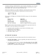
Dial Backup Message
When dial backup occurs (either automatically or by operator intervention), the following
message will flash on the front panel LCD of both modems if the TIA/EIA status screen is
displayed:
This message will clear when the modem returns to the leased line. If you want to clear the
message while the modem is still in dial backup mode, press the ENT pushbutton.
Содержание Alliance V.32
Страница 182: ...0049 2702 XXX Alliance Series Modems USER MANUAL 08 05 2010 Rev A Page 178 of 197 ...
Страница 185: ...0049 2702 XXX Alliance Series Modems USER MANUAL 08 05 2010 Rev A Page 181 of 197 ...
Страница 189: ...0049 2702 XXX Alliance Series Modems USER MANUAL 08 05 2010 Rev A Page 185 of 197 Figure D 1 Connector pin assignments ...


