Supplied By www.heating spares.co Tel. 0161 620 6677
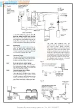
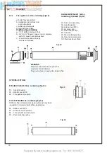
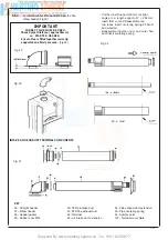
INTAKE AND EXHAUST TERMINAL COMPONENTS
19
5.5.2
Locate the rubber Ø 100 and Ø 60 into the fl ue
elbow header (Fig 30).
- Cut the inner fl ue duct (60 mm) at right
- angles to a length equal to W + 264 mm
Insert from cut end Reassemble the
two tubes Insert centering spring 65 Must
be
de-burred
- Reassemble together inner and outer fl ue
duct insert centering spring.
KEY
56 - Straight header
57 - Elbow header
58 - Header gasket
59 - Rubber seal Ø 60
60 - STD air intake duct
61 - STD fl ue exhaust duct
62 -Terminal
63 - air intake duct extension
64 - Flue exhaust duct extension
65 - Pipe centering spring
66 - Sample point
127 - Terminal cover plate
Fig. 30
Fig. 32
Fig. 31
Fig. 29
IMPORTANT
CORRECT FLUE MUST BE USED .
Check Spigot Distance ( approx 35mm )
on STARTER HEADER.
Ensure Flue is fi tted together correctly,
supported and fi rmly secured
. (Fig.29).
Содержание HE Primary AAA
Страница 16: ...Supplied By www heating spares co Tel 0161 620 6677 17 Fig 18...
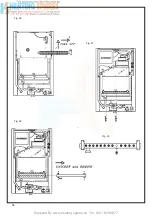
Страница 31: ...Supplied By www heating spares co Tel 0161 620 6677 Fig 58 32 Fig 56 Fig 57...
Страница 33: ...Supplied By www heating spares co Tel 0161 620 6677 34 Fig 60 Fig 61 Fig 62 Fig 63...
Страница 36: ...Supplied By www heating spares co Tel 0161 620 6677 Section 9 ELECTRICAL SYSTEM DIAGRAM Fig 94 37...
Страница 42: ...Supplied By www heating spares co Tel 0161 620 6677 section 10 EXPLODED PARTS DIAGRAM 43...

