Supplied By www.heating spares.co Tel. 0161 620 6677
6
SECTION 1
INTRODUCTION
1.1
The CSI Primary is a gas fi red room sealed
fan assisted condensing heating boiler suit-
able for fully pumped open vented or sealed
system central heating and domestic hot
water systems.
1.2
The provision of stored domestic hot
water
is
possible by the addition of
an indirect cylinder with ‘Y’ or ‘S’ plan
controls
The
data badge is placed on the
front
panel.
1.2.1
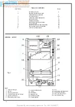
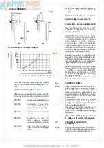
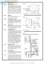
Fig 1 illustrates the general layout of
components.
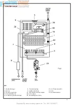
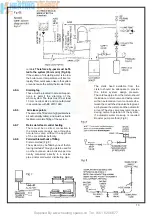
Fig.2 illustrates the operating principals
described in section 2.
SECTION 2
DESCRIPTION OF CONTROL SYSTEM
AND SEQUENCE OF OPERATION
2.1
If the main neon is on with a demand for
heat to the system (radiators etc ) the fan
operates via the pressure switch and sends a
signal back to the ignition board that the fan
is running at maximum speed.
2.2
The spark ignition system is powered which
in turn commences the spark ignitor to
operate and light the burner. At this point
the ignition board opens the gas valve to light
the burner.
2.2.1
When the electrode/sensor senses the sig nal
of the burner the spark ignition stops.
2.2.2
From the minimum gas rate setting
the boiler increases to the maximum
permissible pressure over a period
of 3 to 4 seconds and will remain at
its maximum required power until its
maximum regulated temperature.
2.2.3
When the boiler thermostat is satisfi ed the
boiler will go to rest mode, the burner is shut
down and the pressure switch will return
back to its rest mode.
2.2.4
As the heating sensor reaches temperature
the gas burner power modulates down,
the fan speed. When starting, the fan will
always start at maximum speed.
2.2.5
The boiler is fitted with an anti-cycling
device on the control board. This delays
the boiler from re-firing over a 2/5 minute
period.
2.3 GENERAL
FUNCTION
2.3.1
The gas valve boiler output settings may
be adjusted to requirements other than
factory settings
2.3.2
Air is drawn by the fan for combustion
2.3.3
he fan also forces exhaust gas through the fl ue
to the outside, this creates a lesser pressure
in the sealed combustion cham
ber, thus
sucking in combustion air through the inlet duct
2.3.4
The boiler water temperature is automati
cally
controlled by a built in thermostat
2.3.5
Interior space temperature is set by the room
thermostat to be installed in the heat ing system The
boiler already carries con nection terminals for this
thermostat, as well as for a timeclock The burner
contin ues to operate until it is stopped by the
timer or one of the thermostats
2.3.6
When the room thermostats and/or timer intervene
the burner shuts down The fan stops and the pump
off via the pump overrun.
2.3.7
The condensate trap is fi tted with a block age safety
sensor This prevents the boiler operating should there
be a blockage in the condensate discharge trap.
2.3.8
An overheat cut off thermostat set slightly higher
than the heat thermostat acts to turn off the burner to
resetable “lockout” (Fig 50) .
SECTION 4
GENERAL REQUIREMENTS
4.0
SAFETY
Gas Safety (Installation and Use)
Regulations, 1994 and amended 2000.
It is law that all gas appliances are installed
and serviced by a CORGI registered installer in
accordance with the above regulations and these
installation instructions. All CORGI registered
installers carry a CORGI I.D. card and have a
registration number. Both should be recorded in
your boiler log book. You can check your installer
by calling CORGI direct on: 01256 732300.
Failure to install appliances correctly could lead to
prosecution. It is in your own interest, and that of
safety, to ensure the law is complied with. Check
the boiler and flue is the correct type for installation.
The installation of the boiler MUST be in
accordance with the latest I.E.E. (BS 7671) Wiring
Regulations, local building regulations, bye-laws
of the local water authority, the building regulations
and the Building Standards (Scotland) and any
relevant requirements of the local authority.
authority, the building regulations and the Building
standards (Scotland) and any rele vant requirements
of the local authority.
4.1
GENERAL INFORMATION
Both the user and the manufacturer rely
heavily on the installer, whose job it is to in
stall the
combination boiler and connect it to a correctly
designed heating system Ac
quaint yourself
with the British Standards concerning installation
requirements If you need advice on any points
your Ravenheat Technical Services Offi ce would be
pleased to help It is recommended that tools suitable
Содержание HE Primary AAA
Страница 16: ...Supplied By www heating spares co Tel 0161 620 6677 17 Fig 18...
Страница 31: ...Supplied By www heating spares co Tel 0161 620 6677 Fig 58 32 Fig 56 Fig 57...
Страница 33: ...Supplied By www heating spares co Tel 0161 620 6677 34 Fig 60 Fig 61 Fig 62 Fig 63...
Страница 36: ...Supplied By www heating spares co Tel 0161 620 6677 Section 9 ELECTRICAL SYSTEM DIAGRAM Fig 94 37...
Страница 42: ...Supplied By www heating spares co Tel 0161 620 6677 section 10 EXPLODED PARTS DIAGRAM 43...

