Supplied By www.heating spares.co Tel. 0161 620 6677
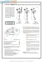
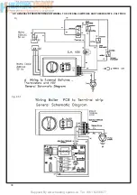
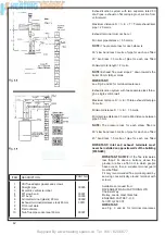
Fig. 59
33
7.10.2
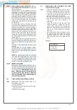
Detach the wire from electrode and then unscrew
the nut that secures it to the burner and remove
.(Fig.61).
7.10.3
Replace with new electrode in reverse order.
7.14
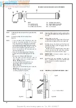
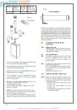
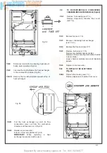
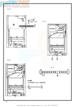
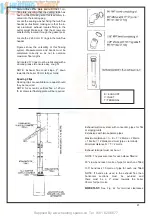
TO REMOVE/REPLACE THE INJECTORS
Fig.62-63).
7.14.1
Remove the front casing and the depression
chamber front cover (sect.7.3,& 7.4)
7.14.2
Unscrew the union and the 4 screws securing
the manifold at the burner .
7.14.4
Pull the manifold up and out from the
combustion chamber (Fig 62).
7.14.5
Unscrew and replace the injectors and their
seals (Fig. 63).
7.14.6
Replace in reverse order.
7.14.7
Relocate the grommet, sealing the gas supply
pipe to the casing taking care not to damage it
Replace if necessary.
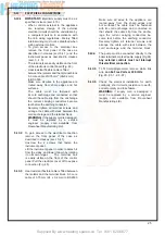
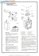
7.15.6
Pull the burner forward and remove (Fig.64).
7.15.7
Replace in reverse order.
IMPORTANT:
When refi tting the burner make
sure that the pins at the rear of the
combustion chamber locate into the slots
made on the rear of the burner
7.16
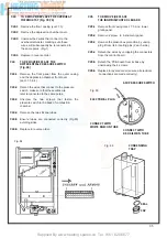
TO REMOVE/REPLACE THE GAS VALVE
(Fig.
51)
7.16.1
Remove front casing panel (sect 7.3) and
remove the lower grating.
7.16.2
Remove the 2 screws that fasten the
instrument panel .
7.16.3
Lower the instrument panel down
by rotating it on its own hinges.
7.16.4
Disconnect the electrical connections from
the gas valve and modulator.
7.16.7
Remove the eight screws (four per side) that
connect the gas valve to the gas pipelines and
then remove it from its seat.
7.16.8
Replace in reverse order, always using
new
seals.
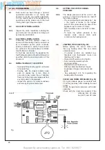
7.19
TO REMOVE/REPLACE THE HEATING
CONTROL
THERMOSTAT
7.19.1
Remove the front casing (sect. 7.3)
and remove the lower gratin panel,
lower down the instrument panel .
7.19.2
Remove the 2 screws that fasten the
instrument panel, and lower it panel down
by rotating it on its own hinges.
7.19.3
Remove the top of control box cover by
unclipping it from its 4 locate pins.
7.19.5
Pull off the thermostat knobs and unscrew
lock nut which fastens the potentiometer to
the instrument panel.
7.19.6
Detach all the connectors from PCB board.
7.19.7
Replace in reverse order.
7.15 TO REMOVE/REPLACE THE BURNER
7.15.1
Remove the front casing and the depression
chamber front cover
(sect.7.3 & 7.4)
7.15.4
Remove the injectors manifold as described
in sect. 7.14
7.15.5
Remove the two screws securing the
burner to the combustion chamber.
Содержание HE Primary AAA
Страница 16: ...Supplied By www heating spares co Tel 0161 620 6677 17 Fig 18...
Страница 31: ...Supplied By www heating spares co Tel 0161 620 6677 Fig 58 32 Fig 56 Fig 57...
Страница 33: ...Supplied By www heating spares co Tel 0161 620 6677 34 Fig 60 Fig 61 Fig 62 Fig 63...
Страница 36: ...Supplied By www heating spares co Tel 0161 620 6677 Section 9 ELECTRICAL SYSTEM DIAGRAM Fig 94 37...
Страница 42: ...Supplied By www heating spares co Tel 0161 620 6677 section 10 EXPLODED PARTS DIAGRAM 43...

