INSTRUCTION, USE AND
MAINTENANCE MANUAL
GB
Page 33 of 64
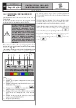
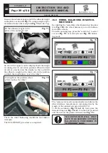
Fig. 60
On reaching the 2 fixed ar-
rows, fit the adhesive weight
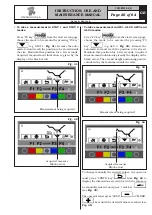
The fact that the weight fitting position is no longer at
12 o’ clock (see
Fig. 61
) is automatically offset.
If the adhesive weight has to be hidden behind spokes,
refer to “weights hidden behind spokes mode” in
Chapt. 18.
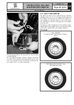
Fig. 61
Fit weight on the position where
pliers touches the wheel
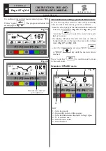
Check wheel balancing conditions by making a trial
spin. The display screen will show an unbalance reset.
The STATIC procedure is completed.
15.4 Measuring the unbalance with auxil-
iary programs
The available functions permit selecting the appropri-
ate weight positions to be placed in positions different
to the standard ones (dynamic unbalance).
The ALU programs measure rims by means of pre-set
data in the wheel balancer.
The measurements entered by the operator will there-
fore be automatically corrected by the machine accord-
ing to the selected program.
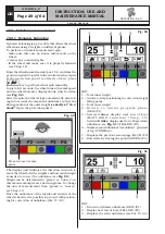
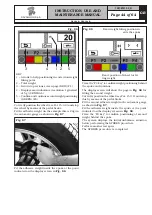
From the program start page, press "F2 key".
The monitor shows a window with possible selection
modes. Select the desired function by means of the “F3
key”
and enter the measurements.
POSSIBLE SELECTABLE FUNCTIONS
The ALU-S 1 function permits balancing wheels with
light alloy rims by fitting adhesive weights on the outer
side and weight with clip on inner side of wheel (at 12
o’ clock). Enter the measurements (see par. 15.1) and
proceed as described in par. 15.4.1 (the inner weight
is with clip).
The ALU-S 2 function permits balancing wheels with
light alloy rims by fitting two adhesive weights on the
outer and inner sides of the rim (the inner weight is
at 12 o’ clock).
Enter the measurements (see par. 15.1) and proceed as
described in par. 15.4.1 (the inner weight is adhesive).
1297-M010-0_R
G2.124R - GP2.124R
RAVAGLIOLI S.p.A.


