GB
Page 30 of 64
INSTRUCTION, USE AND
MAINTENANCE MANUAL
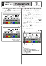
When the wheel balancer display screen shows
and
the
exact position
has been reached for
one side and for the other. The fitting point has been
found. Now the unbalance can be corrected by fitting
the necessary weight.
Once the wheel has been correctly positioned, fit the
weight indicated by the machine on both sides of the
wheel. The program automatically indicates the best
weights to be fitted and rounds these off according to
their position.
Should wheel dynamic unbalance be quite high and the
weight to be fitted not available, the SPLIT procedure
can be used so as to correct the dynamic unbalance
dividing the weight amount into two smaller weights
(Chapt. 17).
After fitting the weights, check the wheel balancing
conditions and make a trial spin.
The STANDARD unbalance calculation procedure is
now completed.
15.3.2 Positioning the correction weights on
the wheel
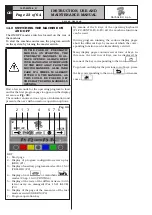
The weights must be positioned at the top part of the
wheel, at 12 o’ clock, so that the unbalance will be at
the bottom and the weight fitting point will be at the top.
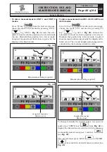
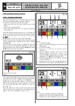
When the wheel balancer display screen shows
or
this means you are
very far
from the point where
the counterweight is to be positioned.
Wheel position is over 30° from the exact fitting point.
When the wheel balancer display screen shows
or
this means you are
not far
from the point where
the counterweight is to be positioned.
Wheel position is within 30° from the exact fitting point.
15.3.3 ALU-S procedure
Make sure there are no stones and/or mud on the
wheel. Remove any counterweights.
Fit the wheel and make sure it is properly fastened
(see Par. 12).
Determine the wheel dimensions using the specific
automatic rod (see Par. 15.1.1).
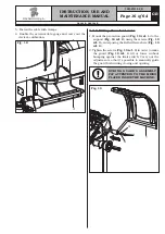
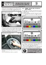
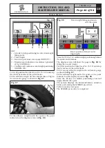
After data entry, close the protection guard to automati-
cally start wheel spin (see
Fig. 52
).
After the spin, the wheel stops automatically, taking
into account the measured unbalance so that the fitting
position of the outer weight is around at 12 o' clock.
Open the protection guard.
Fig. 52
Press in case of emer-
gency
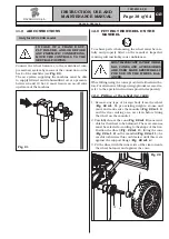
The display unit indicates the direction in which to
move the wheel to fit the weights and how much weight
is needed to correct the unbalance (see
Fig. 53
).
Once the unbalance value of the inner and outer wheel
side is known, the wheel can be positioned by turning
it in the direction indicated by the arrows until the
correct position is reached (see Par. 15.3.2).
Once correct position has been reached, press the
pedal brake to stop the wheel.
G2.124R - GP2.124R
RAVAGLIOLI S.p.A.
1297-M010-0_R

