INSTRUCTION, USE AND
MAINTENANCE MANUAL
GB
Page 31 of 64
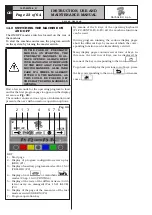
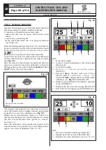
Fig. 53
1
2
3
4
5
KEY
1 – R e t u r n t o i n i t i a l p r o g r a m p h a s e
(RED) (F1)
2 – Display next row of keys (MATCHING PROCE-
DURE and HIDDEN WEIGHTS) (YELLOW) (F2)
3 – Displays exact unbalance (resolution 1 g instead
of 5 g) (CENTRAL)
4 – Displays the previous screen page (BLUE) (F3)
5 – Performs spin with protection guard closed
(GREEN) (F4)
6 – Permits performing the ECO-WEIGHT program
(B)
6
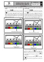
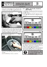
Remove the automatic rod and fit the adhesive weight
inside pliers as shown in
Fig. 54
.
Fig. 54
Fit the adhesive weight in the
pliers of the automatic rod
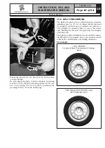
The nearing of the weight to correction position is indi-
cated by an arrow that appears on the side of the wheel
on which work is being done. When two fixed arrows
are reached (see
Fig. 55
) fit the weight in the position
where the weight pliers touch the wheel (see
Fig. 56
).
Fig. 55
On reaching the 2 fixed ar-
rows, fit the adhesive weight
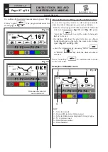
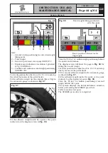
The fact that the weight fitting position is no longer at
12 o’ clock (see
Fig. 56
) is automatically offset.
If the adhesive weight has to be hidden behind spokes,
refer to “weights hidden behind spokes mode” in
Chapt. 18.
Fig. 56
Fit weight on the position where
pliers touches the wheel
Repeat the wheel and weight positioning procedure
for the inner side of the wheel as well. At the end of
the procedure, the wheel balancing conditions can be
checked by performing a trial spin.
The ALU-S procedure is completed.
1297-M010-0_R
G2.124R - GP2.124R
RAVAGLIOLI S.p.A.


