GB
Page 14 of 64
INSTRUCTION, USE AND
MAINTENANCE MANUAL
1
2
2
3
4
5
6
1
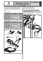
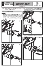
4. Close the pneumatic mandrel by means of the pedal
to access the key socket (Fig.(
Fig. 11
).
Fig. 11
5. Press the brake pedal and at the same time block
the external mandrel using the wrench supplied
(
Fig. 12
).
Fig. 12
REMOVAL
• Close the pneumatic mandrel by means of the pedal
to access the key socket (
Fig. 11
).
• Press the brake pedal and at the same time release
the external mandrel by using the wrench provided
(
Fig. 12
).
• Remove the external mandrel, open the pneumatic
mandrel by means of the pedal provided and loosen
the internal mandrel using the special wrench
(
Fig. 9
).
9.3.3 Fitting of external data gauge (option-
al)
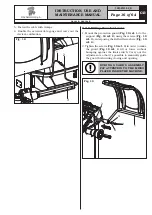
1. Unscrew the fastening screws of the equalizer's
support (
Fig. 13 ref. 1
), being very careful about
holding the same support.
2. Unscrew the 3 screws (
Fig. 13 ref. 2
) to the gauge
bracket (
Fig. 13 ref. 3
) and in the special inserts
placed on the rear side of the frame.
Lock the gauge arm (
Fig. 13 ref. 4
) by screwing
the 2 screws provided (
Fig. 13 ref. 5
). Lock these
screws with the nuts (
Fig. 13 ref. 6
) so that the
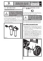
gauge arm are levelled out as the mandrel (see
Fig. 14
).
Fig. 13
3. Also make sure the gauge tip (
Fig. 14 ref. 1
) is
positioned at the centre of the mandrel.
Fig. 14
G2.124R - GP2.124R
RAVAGLIOLI S.p.A.
1297-M010-0_R


