30
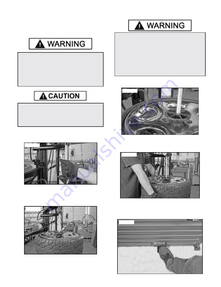
STAGE ONE / WHEEL RESTRAINT
(R980X-AT ONLY)
As an added safety precaution, a wheel restraint devise has
been added to protect operators during tire inflation.
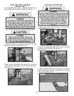
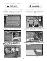
1. Raise the left helper and support assembly and insert the
restraint devise as shown. (See Fig. 16.2)
2. Make sure the restraint tool is centered in the center hub
of the wheel then press down on the left hand control valve.
(See Fig. 16.3)
STAGE TWO / BEAD SEALING
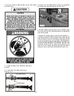
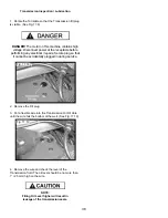
1. Position valve stem in front of operator and connect the
inflation hose. (See Fig. 16.4)
2. Hold tire up against upper edge of the wheel. Be sure tires
top bead is over the bottom of the valve stem.
(See Fig. 16.5)
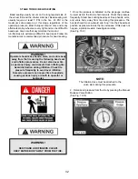
3. Depress Inflation Pedal and hold about one second to
begin air flow through tire valve, and hold briefly – less than
1 full second. (See Fig. 16.6)
WARNING!
This devise is a restraint devise only. It will not
protect operators in the event of catastrophic tire/
wheel rupture or failure. Always use extreme
caution during the inflation procedure. As an
added safety precaution, safety cages that conform
to OSHA standard 1910.177 are recommended.
CAUTION!
Hold the restraint tool firmly in place when
installing and/or removing from the left helper
assembly. The unit can drop suddenly to the floor.
Be sure to keep feet clear at all times.
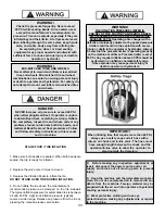
WARNING!
Operator should keep hands, arms, and entire body
away from the tire during the following bead seat
and inflation procedures. Do not stand over tire,
as personal injury could result. from inflating tire.
Avoid distraction during inflation. Check tire
pressure frequently to avoid over inflation.
Excessive pressure can cause tires to explode,
causing serious injury or death to operator or
bystander.
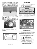
Fig. 16.2
Fig. 16.3
Fig. 16.4
Fig. 16.5
Fig. 16.6
Содержание R980X
Страница 39: ...39 ...
Страница 48: ...48 ...
Страница 49: ...49 RECORD ALL MAINTENANCE NOTES AND SERVICE HISTORY HERE ...
Страница 50: ...50 TIRE AND WHEEL DATA ...
Страница 51: ...51 This page intentionally left blank ...


