background image

43

4

1

2

3

18

19

20

21

22

17

22

23

15

16

7

14

13

9

10

12

11

8

6

5



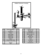
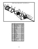
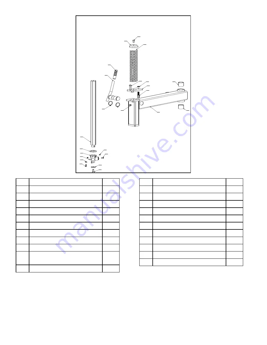
R980X-AT Vertical Arm  Assembly

Ref

Product Description

qty

1

Cap

1

2

Bolt M8 x 20

1

3

Spring

1

4

Plastic handle

1

5

Locking lever

1

6

Snap ring 42

2

7

Vertical shaft

1

8

Spacer

1

9

Mount-demount Head

1

10 Mount-demount Head plastic 

protector

1

11

Roller

1

12

Roll Pin 6 x 24

1

13

Bolt M10 x 25

1

14

Flat washer

1

15

Set screw M10 x 16

2

16

Set screw M10 x 10

2

17

Nut M10

1

18

Bolt M10 x 45

1

19

Nut M12

1

20

Plate

1

21

Locking bolt 

1

22

Bushing

2

23

Horizontal arm

1

Содержание R980X

Страница 1: ... without reading this manual and the important safety instructions shown inside 1645 Lemonwood Dr Santa Paula CA 93060 USA Toll Free 1 800 253 2363 Tel 1 805 933 9970 Fax 1 805 933 9160 www rangerproducts com Please read THE entire CONTENTS OF THIS MANUAL prior to installation AND OPERATION BY PROCEEDING YOU AGREE THAT YOU FULLY UNDERSTAND AND COMPREHEND THE FULL CONTENTS OF THIS MANUAL Forward th...

Страница 2: ...es not extend to t defects caused by ordinary wear abuse misuse shipping damage improper installation voltage or lack of required maintenance t damages resulting from purchaser s neglect or failure to operate products in accordance with instructions provided in the owner s manual s and or other accompanying instructions supplied t normal wear items or service normally required to maintain the prod...

Страница 3: ... levels are high 3 THIS SYMBOL POINTS OUT IMPORTANT SAFETY INSTRUCTIONS WHICH IF NOT FOLLOWED COULD ENDANGER THE PERSONAL SAFETY AND OR PROPERTY OF YOURSELF AND OTHERS AND CAN CAUSE PERSONAL INJURY OR DEATH READ AND FOLLOW ALL INSTRUCTIONS IN THIS MANUAL BEFORE ATTEMPTING TO OPERATE THIS MACHINE Table of Contents Page Warranty 2 Operator Protection 3 Section 1 Definitions of Hazard Levels 4 Owner ...

Страница 4: ...installation instructions t Make sure installation conforms to all applicable Local State and Federal Codes Rules and Regulations such as State and Federal OSHA Regulations and Electrical Codes t Carefully check the unit for correct initial function t Read and follow the safety instructions Keep them readily available for machine operators t Make certain all operators are properly trained know how...

Страница 5: ...a live terminal This is for ground only 11 Danger The motor on this machine contains high voltage Disconnect power at the receptacle before performing any electrical repairs Secure plug so that it cannot be accidentally plugged in during service 12 Warning Risk of explosion This equipment has internal arcing or sparking parts which should not be exposed to flammable vapors This machine should not ...

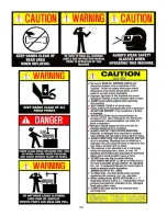
Страница 6: ...l as tire or wheel failure may result during inflation Explosion from failure may result in severe injury or death of the operator and bystanders Inflation ALWAYS be sure the bead opposite the tool is in the drop center before rotating the tire when demounting or mounting to avoid damage to the tire beads ALWAYS follow all applicable Local State and Federal Codes Rules and Regulations such as the ...

Страница 7: ... 4 3 10 Bead Breaker Foot Pedal See Fig 4 3 11 Wheel Clamp Foot Pedal See Fig 4 3 12 Lube Bottle Brush 13 Turntable 14 Wheel Clamps 15 Mount Demount Head 16 Turbo Blast Hose Assembly 17 Helper Disc 18 Drop Center Tool 19 Assist Tower Controls 20 Assist Arm 21 Vertical Shaft 22 Vertical Arm Assembly 23 Vertical Shaft Lock Handle 24 Vertical Shaft Spring 25 Voltage Selector Switch Located on Rear of...

Страница 8: ...nternal Wheel clamping Capacity 11 24 279 mm 610 mm External Wheel clamping Capacity 10 23 254 mm 584 mm Turntable Tire Width Capacity Mounting 4 5 17 5 114 mm 444 mm Bead Breaker Tire Width Capacity Demounting 1 14 25 mm 356 mm Maximum Tire Diameter 48 1219 mm Shipping Weight R980X 620 lbs 282 Kg R980X AT 680 lbs 309Kg Specifications are subject to change without notice NOTE Internal and External...

Страница 9: ...rvice activity Safety glasses with side shields goggles or face shields are acceptable Remember to report any shipping damage to the carrier and make a notation on the delivery receipt Uncrating Instructions 1 Carefully cut the plastic wrapping and remove 2 Carefully cut open the top of the cardboard box Either lift off box or cut side panel and remove See Fig 6 3 3 Using a crow bar or pry bar loc...

Страница 10: ...ssist Tower 5 Either cut or unscrew the metal strapping holding the Air Tower Tank and Assist Tower to the pallet Using a fork lift or shop crane remove both towers from the pallet and set aside Secure both towers so they can not fall See Fig 6 7 6 Remove the four front and rear Bolts and Nuts holding the tire changer from the pallet See Figs 6 8 6 9 CAUTION Handling of the machine must be perform...

Страница 11: ...d should be away from oil grease brake lathe chips etc Avoid areas where bystanders and customers may be present Machine size is approximately 36 W x 48 D X 80 H R980X R980X AT These measurements are the tire changer s working range Persons other than specially trained and authorized operators are expressly forbidden to enter this area Choose a safe location that is in compliance with current work...

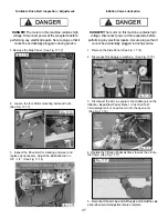
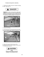
Страница 12: ...b Fittings on the under side of the Air Tank Tower using the supplied Hose Clamps See Fig 8 3 6 Connect the other end of the Air Inflation Hose to the Push to Connect Fitting inside the Air Inflation Box Assembly See Fig 8 4 Swing Arm Vertical Shaft Mount demount Head Assembly 1 Raise the Vertical Shaft Mount demount Head assembly to the highest position and lock it in place by Pushing the Locking...

Страница 13: ...components must be performed only with an appropriate lifting device such as a forklift or shop crane Only personnel who are experienced and qualified on material handling procedures should handle any transportation or moving of machine components CAUTION Keep the Assist Tower Supported by the lifting strap or chain until ALL Assist Tower Bracket Bolts have been Tightened 4 Using a fork lift or ot...

Страница 14: ... loosely tightened If desired remove the Tower Cylinder Cover for easier access See Fig 8 12 13 7 Insert the Top Bracket Bolts that connects the Assist Tower to the Swing Arm Bracket See Fig 8 14 NOTE Keep the other Tower Bracket Bolts loose until all Brackets and holes are aligned 8 Install the Nuts from the under side of the Swing Arm Bracket See Fig 8 15 Fig 8 11 Fig 8 12 Fig 8 13 Fig 8 14 Fig ...

Страница 15: ...solid and level and supported evenly on all anchor points Solid shims may be used if necessary See Fig 8 18 Section 9 Air Source This model requires a 14 to 15 CFM air source at 165 PSI maximum pressure The safe operating pressure range for this model is between 140 PSI and 165 PSI at the machine A 1 4 ID hose or pipe for connection to the machine is satisfactory Sufficient air pressure assures go...

Страница 16: ... Have a licensed electrical technician perform any necessary changes to the power source and power cord before plugging in the unit The elec trical source must have a solid connection between ground and building ground Warning Guard against electric shock This equipment must be grounded while in use to protect the operator from electric shock Never connect the green power cord wire to a live termi...

Страница 17: ...Check the voltage phase and proper amperage requirements for the motor shown on the motor plate Wiring should be performed by a certified electrician only IMPORTANT NOTE YOUR MACHINE HAS A DUAL VOLTAGE MOTOR and can be run on either 110 or 220 volts STANDARD WIRING IS 110 VOLTS See below before connecting 220 volts to your machine or serious damage to the motor electronics will result Have a licen...

Страница 18: ...ut not on the rim and not on the tire sidewall 5 Pull the bead breaker shoe away from the machine and roll the wheel into position 6 Position the bead breaker shoe against the tire next to but not on the rim Press the breaker pedal to actuate the shoe and loosen the bead It may be necessary to loosen the bead in multiple locations around the tire See Fig 11 2 7 Turn wheel around and repeat procedu...

Страница 19: ...Narrow Side and Wide Side flanges 3 The tire must ALWAYS be demounted or mounted with the wheel positioned on the turntable with the Narrow Side facing upward and the deepest part of the Drop Center facing upward WARNING The wheel illustrated above in diagram A has little or no prominent drop center These are not DOT approved wheel configurations The tire or wheel or both can be damaged during mou...

Страница 20: ...e top See Fig 11 9 13 After the wheel is secured to the Turntable pull the Overhead Swing Arm into position use the large adjusting Knob to position the Mount Demount Head directly over the edge of the rim See Fig 11 10 20 NOTE Clamp steel wheels from the inside clamps push outward against wheel Clamp mag and custom wheels from the outside Clamps push inward against the outside rim edge Refer to t...

Страница 21: ...ay from the wheel to lower the bead into the Drop Center while lifting up on the Table Top Pedal to rotate the turnable counter clockwise See Fig 11 15 NOTE This clearance will be maintained as long as the Vertical Shaft remains locked The operator may swing the arm out of the way and back into place again without needing to reposition the head when changing a like set of wheels The tool clearance...

Страница 22: ...g Tool down until the upper bead is solidly above the rim Continue rotating the wheel clockwise until the upper bead is completely demounted See Fig 11 19 11 21 DANGER The Bead Lifting Tool and demount head may encounter resistance or come under load at times during the mount and demount procedures Keep one hand firmly on the tool to avoid possible tool kick back Use the reversing feature lift tab...

Страница 23: ...Bead Lifting Tool down toward the wheel to lift the tire bead up and over the left duckbill side knob portion of the Mount Demount Head Hold the Bead Lifting Tool in this position See Fig 11 24 11 25 23 Depress the Table Top Pedal to rotate the wheel See Fig 11 26 24 The Mount Demount Head will guide the bead up and over the edge of the wheel Continue rotation until the lower bead is demounted See...

Страница 24: ...pposite the valve hole or mounted on the valve stem On these wheels the beads should be loosened at the valve hole on both upper and lower sides first See Fig 12 2 DEMOUNTING TUBE TYPE TIRES 1 After both tire beads are loosened lubricate the beads and rim liberally 2 Position the demount head and bead lifting tool as described earlier paying careful attention not to pinch the tube Depress the tabl...

Страница 25: ...dths for tire sizes DANGER Attempts to force a bead seat on mis matched tires and wheels can cause the tire to violently explode causing serious personal injury or death to operator and or bystanders WARNING Never mount a tire and wheel handed to you by anyone without checking both tire and wheel for damage and compatibility Be extra cautious of persons without knowledge of tire service Keep bysta...

Страница 26: ...13 6 6 For the top bead rotate the Table Top until the valve stem is directly across from the Mount Demount Head Lift the upper bead above the right side of the Mount Demount Head and below the knob See Fig 13 7 13 8 8 With the Bead Lifting Tool press down on the tire to hold the upper bead in the drop center See Fig 13 9 Note Low Profile Tires may require a second Bead Lifting Tool 26 Fig 13 4 Fi...

Страница 27: ...ar the Mount demount Head to hold the tire in the drop center See Fig 13 14 Note Low Profile Tires may require a Use of the Bead Lifting Tool 11 Depress the Table Top Pedal and rotate the tire until the bead is mounted See Fig 13 15 13 17 27 Fig 13 11 Fig 13 10 Fig 13 12 Fig 13 13 NOTE The Following Procedures show optional equipment being used The Tire Changer you are using may not have the Assis...

Страница 28: ...making the tire unsafe and or creating the risk of injury DANGER Check inflation gauge for proper operation Accurate pressure readings are important to safe tire inflation Refer to the Operating Maintenance section of this manual for instructions If the rim has been clamped from the outside for tire mounting release the clamps once bead seal is obtained lift the tire and move the clamps to the cen...

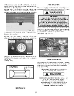
Страница 29: ...g beyond 60 PSI smaller tires may reach higher pressures It is the operators responsibility to follow all instructions and to control inflation pressure as specified in these instructions See Fig 16 1 Stages of Inflation Review the following descriptions and diagrams carefully Refer to them as necessary during bead sealing bead seating and inflation to verify that you are proceeding properly and s...

Страница 30: ...econd See Fig 16 6 WARNING This devise is a restraint devise only It will not protect operators in the event of catastrophic tire wheel rupture or failure Always use extreme caution during the inflation procedure As an added safety precaution safety cages that conform to OSHA standard 1910 177 are recommended CAUTION Hold the restraint tool firmly in place when installing and or removing from the ...

Страница 31: ...ecessary to wait a few seconds for the air storage tank to recover before attempting again If tire and wheel are properly lubricated and operator can not achieve bead seal after a few attempts the valve core should be removed from the valve stem to allow more air flow into the tire to assist with bead seal After bead seal is achieved remove the chuck and reinstall the valve core 31 CAUTION NEVER P...

Страница 32: ...s arms and entire body away from tire during this procedure Tire beads should move outward and pop into their bead seat position as pressure inside the tire increases If this does not happen a problem exists Investigate carefully See Fig 16 9 NOTE The Inflation Hose must be attached to the valve stem during this procedure 2 Release air pressure from the tire by pressing the Manual Release Valve Bu...

Страница 33: ...to operator or bystanders DANGER NEVER increase air pressure to exceed 40 PSI when attempting Bead Seat If operator is unable to obtain Bead Seat something is wrong Deflate tire completely inspect tire and wheel correct any problems found re lubricate both tire beads and reattempt Bead Seal and Seat procedures Follow and follow all safety instructions in this manual and on machine WARNING MIS MATC...

Страница 34: ...d covers are in place t Check for worn damaged or missing parts including grips and protective covers Replace them before allowing the unit to be used t On a daily basis inspect the unit and check to be certain that all systems are operating normally Follow detailed inspection and testing procedures as specified for various components at regular intervals MONTHLY t Lubricate the arm Pivot Pin See ...

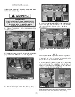
Страница 35: ...r supply when service adjustments are complete NOTE This adjustment will require two persons to perform 1 With the Air source connected depress the Bead Breaker Pedal to operate the Bead Breaker 2 Observe the site glass and adjust the oil flow of the oiler by turning the Oiler Adjustment Knob so that 2 3 drops of oil drip through the site glass for each operation of the Bead Breaker Pedal See Fig ...

Страница 36: ...ati cally Both gauges should read 60 PSI 5 PSI 5 If the pressure exceeds 60 PSI adjust the knob on the regulator by lifting the locking cover and turning COUNTERCLOCKWISE After adjustment is made secure cover in the locked position 6 Repeat steps 1 6 Re adjust if necessary 7 After pressure limit has been set check the manual release valve function by pressing the button and releasing pressure from...

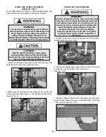
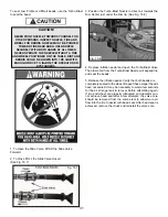
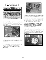
Страница 37: ... The motor on this machine contains high voltage Disconnect power at the receptacle before performing any electrical repairs Secure plug so that it cannot be accidentally plugged in during service 1 Remove the Side Panel See Fig 17 12 2 Disconnect Air Supply to machine See Fig 17 15 3 Disconnect the Air Line going to the middle port on the Inflation Bead Blast Pedal Place 1 2 oz SAE 10W non deterg...

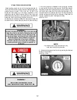
Страница 38: ...l repairs Secure plug so that it cannot be accidentally plugged in during service 2 Remove the Fill plug 3 Put a flexible wire into the Transmission Oil Fill Hole until the wire hits the bottom of the well See Fig 17 19 4 Remove the wire and check the level of the Transmission fluid The oil level should be no more than 1 25 mm high on the wire NOTE Filling Oil Level higher will result in leakage o...

Страница 39: ...39 ...

Страница 40: ... 65 66 61 60 63 88 62 59 54 56 52 57 58 51 50 49 48 53 70 47 71 46 55 44 45 72 43 73 75 37 38 35 32 39 31 34 29 36 28 41 30 26 42 27 25 23 24 40 74 22 20 18 21 19 17 16 10 8 15 7 4 9 39 25 33 67 25 25 64 51 92 93 94 91 2 91 3 91 91 5 91 4 91 1 95 91 6 96 91 7 98 R980X Main Assembly ...

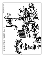
Страница 41: ...breaker arm 1 53 Bolt M16 x 120 1 54 Bead breaker spring 1 55 Bead breaker cylinder bracket 1 56 Snap ring 38 2 57 Bead breaker blade pin 1 58 Bolt 1 59 Bolt 1 60 Water seperater Oiler 1 61 Pressure gauge 1 62 Bracket 1 63 Screw M8 x 20 2 64 Lube bracket holder 1 65 Lube bracket 1 66 Plastic tower cover 1 67 Lock washer 10 5 68 Bolt M10 x 35 2 69 Bolt M10 x 50 3 70 Nut M24 1 71 Cylinder rod spacer...

Страница 42: ...acer 1 8 Bolt M8 x 60 1 9 Nut M8 3 10 Bolt M6 x 20 8 11 Spring 1 12 Flat washer 12 2 13 Bolt M6 x 16 6 14 Spring guide 1 15 Pedal pivot rod 1 16 Carter key 3 2x14 2 17 Locking Nut M6 9 18 Switch linkage 1 19 Switch arm 1 20 Switch bracket 1 21 Switch cover 1 22 Bead breaker valve 1 22 1 Spool valve 1 22 2 O ring 12 22 3 Spacer 10 22 4 Valve body 2 23 Roll pin 1 24 Valve linkage 1 25 Valve linkage ...

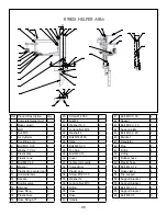
Страница 43: ...stic handle 1 5 Locking lever 1 6 Snap ring 42 2 7 Vertical shaft 1 8 Spacer 1 9 Mount demount Head 1 10 Mount demount Head plastic protector 1 11 Roller 1 12 Roll Pin 6 x 24 1 13 Bolt M10 x 25 1 14 Flat washer 1 15 Set screw M10 x 16 2 16 Set screw M10 x 10 2 17 Nut M10 1 18 Bolt M10 x 45 1 19 Nut M12 1 20 Plate 1 21 Locking bolt 1 22 Bushing 2 23 Horizontal arm 1 ...

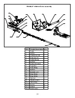
Страница 44: ...ption Qty 1 Pedal 1 2 Spring 1 3 Pedal pivot rod 1 4 Snap ring 12 2 5 Pedal linkage 1 6 Nut M8 1 7 Support bracket 1 8 Regulator 1 9 Hose fitting 1 10 Nut M6 2 11 Bolt M6 x 20 2 12 Hose fitting 1 13 Hose fitting 1 14 Sliencer 3 15 Inflation valve 1 15 1 Valve body 1 15 2 O ring 6 15 3 Spacer 5 15 4 Spool valve 1 ...

Страница 45: ...6 Ref Product Description Qty 1 Hose fitting 2 2 Bolt M8 x 220 12 3 End cap 1 4 Cylinder 1 5 Nut M18 1 6 Seal 2 7 Piston 1 8 Gaskit 1 9 Bushing 1 10 Front cap 1 11 Nut M8 12 12 Bushing 1 13 Seal 1 14 Lock ring 25 1 15 Cylinder rod 1 16 Seal kit ...

Страница 46: ...e 3 19 Hose fitting 90º 3 20 Screw M4 X50 1 21 Nut M4 1 22 Washer 10 5 2 23 Locking Nut M16 1 24 Washer18 2 25 Bolt M16X160 1 26 Slide 1 27 Bolt M8 X 20 1 28 Top Cap 1 29 Bolt M6 X10 7 30 Cover 1 31 Vertical arm guide 1 32 Curved Arm 1 33 Plastic cap 2 34 Screw M12 X 50 1 35 Washer 12 1 36 Locking Nut M15 1 37 Fitting 2 38 Hose 1 39 Hose 1 40 Handle 1 41 Bolt M10 X 30 4 42 Spacer 1 43 Bolt M12 X 4...

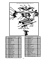
Страница 47: ... washer 12 8 10 Bolt M12 x 35 4 11 Clamp arm 4 12 Clamping plate 1 13 Snap ring 65 1 14 Spacer bushing 4 15 Sliding plate 2 16 Bolt M12 x 80 4 17 Air cylinder 2 17 1 Cylinder Bolt 4 17 2 Nut M8 4 17 3 Cylinder tube 1 17 4 Front cap 1 17 5 Rear cap 1 17 6 Nut M16 1 17 7 Flat washer 16 1 17 8 Gasket 2 17 9 Piston and seal 1 17 10 Piston rod 2 17 11 Cylinder rod seal 2 17 12 Cylinder seal kit 1 18 Bo...

Страница 48: ...48 ...

Страница 49: ...49 RECORD ALL MAINTENANCE NOTES AND SERVICE HISTORY HERE ...

Страница 50: ...50 TIRE AND WHEEL DATA ...

Страница 51: ...51 This page intentionally left blank ...

Страница 52: ... Parts Or Service Contact BendPak Inc Ranger Products 1645 Lemonwood Dr Santa Paula CA 93060 Tel 1 805 933 9970 Toll Free 1 800 253 2363 Fax 1 805 933 9160 www bendpak com www rangerproducts com pn 5900157 ...

Отзывы: