background image

INSTRUCTION MANUAL

• For any further information please contact your local dealer or call:

For spare parts drawings refer to the section “ LIST OF COMPONENTS” enclosed to this manual.

GB

TRANSLATION FROM THE 

ORIGINAL INSTRUCTIONS

- Rev. n. 4 (11/2018)

CAPTURE 4

CAPTURE 4 FI

BUTLER ENGINEERING and MARKETING S.p.A. a s. u.

Via dell’Ecologia, 6 - 42047 Rolo - (RE) Italy

Phone (+39) 0522 647911 - Fax (+39) 0522 649760 - e-mail: [email protected]

7104-M007-4_B

7104-M007-4_B 

Содержание CAPTURE 4

Страница 1: ...r to the section LIST OF COMPONENTS enclosed to this manual GB TRANSLATION FROM THE ORIGINAL INSTRUCTIONS Rev n 4 11 2018 CAPTURE 4 CAPTURE 4 FI BUTLER ENGINEERING and MARKETING S p A a s u Via dell Ecologia 6 42047 Rolo RE Italy Phone 39 0522 647911 Fax 39 0522 649760 e mail Info butler it 7104 M007 4_B 7104 M007 4_B ...

Страница 2: ...e in AUTO mode without PC management _______________________26 11 4 Pedalboard see Fig 16 _______________27 12 0 MACHINE SWITCHING ON AND OFF__ 28 12 1 Smart card for program protection and memory bank______________________28 13 0 USING THE MACHINE_______________ 28 13 1 Preliminary operations Preparing the wheel_______________________________28 13 2 Wheel clamping________________________28 13 2 1...

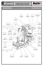
Страница 3: ...lation device 15 Entrainer 16 Pedal for operations assent 17 Activator support KEY 1 Wheel support 2 Upper tool 3 Upper roll 4 Lower roll 5 Lower tool 6 Multifunctional console 7 Pedalboard 8 Complete column 9 Air preparation filter 10 Tubeless inflation unit 11 Locking ring nut 12 Lifting device 13 Console 14 Ring for assembly grease support 15 Pedal operated inflation device 16 Entrainer 17 Peda...

Страница 4: ...k shoes Caution hanging loads Mandatory Operations or jobs to be performed compulsorily Danger Be particularly careful Symbols Description Move with fork lift truck or pallet truck Lift from above Wear safety goggles Warning Be particularly careful possible material damages Note Indication and or useful information CAPTURE 4 CAPTURE 4 FI 7104 M007 4_B ...

Страница 5: ...INSTRUCTION USE AND MAINTENANCE MANUAL GB Page 5 of 67 INFORMATION PLATE LOCATION TABLE CAPTURE 4 CAPTURE 4 FI 7104 M007 4_B ...

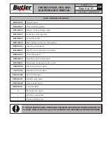
Страница 6: ...cifications plate B4221000 Grounding plate B4244000 Rotating parts danger plate B7189000 Mushroom head push button plate 99990758 Electricity danger plate 710211210 Rotation direction plate 999912430 230V 50 Hz plate 999916311 Rubbish skip label 999918800 Assent pedal label 999918811 Controls label Manufacturer plate Machine nameplate Serial number plate IF ONE OR MORE PLATES DISAPPEAR FROM THE MA...

Страница 7: ...ate for many years without problems thus satisfying Your needs 2 0 INTENDED USE The machines described in this manual and their different versions are tyre changers for car tires and light transport projected to be used exclusively for the mounting demounting and inflation of wheels with dimensions of max diameter of 54 and max width of 15 THIS MACHINE MUST BE USED STRICTLY FOR THE INTENDED PURPOS...

Страница 8: ... through pictorial representations and warnings which placing is indicated in PLATE POSITIONING TABLE at page 5 4 0 GENERAL SAFETY RULES Any tampering with or modification to the machine not previously authorized by the manufacturer ex empts the latter from all responsibility for damage caused by or derived from said actions Removing of or tampering with the safety devices or with the warning sign...

Страница 9: ...r the floor slippery and do not expose such tools to atmospheric agents When operating and servicing this machine carefully follow all applicable safety and accident prevention precautions The machine must not be operated by professionally unskilled persons During inflation do not lean on the tyre or remain above it When beading in the tyre keep hands away from tyre and the rim edge During inflati...

Страница 10: ...hould not be left within reach of children since it is potentially dangerous These ma terials should be deposited in the relevant collection points if they are pollutants or non biodegradable THE BOX CONTAINING THE FIX TURES IS CONTAINED IN THE WRAPPING DO NOT THROW IT AWAY WITH THE PACKING 7 0 MOBILIZATION THE LIFTING EQUIPMENT MUST WITHSTAND A MINIMUM RATED LOAD EQUAL TO THE WEIGHT OF THE MACHIN...

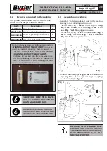
Страница 11: ...ore carrying out the definitive fixing check that all the anchor points are laid down flat and correctly in contact with the fixing surface itself If not so insert shimming profiles between the machine and the fixing lower surface as indicated in Fig 5 Fig 5 a 830 mm b 590 mm Execute 4 holes with 10 mm diameter on the floor by the holes on the bottom floor insert the small blocks excluded from sup...

Страница 12: ...POSITION CAPTURE 4 CAPTURE 4 FI 7104 M007 4_B 8 2 Fixtures contained in the packing The packing case contains also the fixtures box Check that all the parts listed are there Code Description N B1157000 Two faced cone 1 710013421 Reverse wheels protection 1 G1000A124 Bead depressing 28 with en trainer 1 G1000A152 D 14 pin light truck flange 1 Each machine is supplied with an activation kit WARNING ...

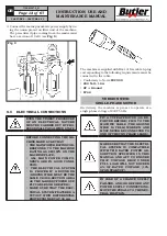
Страница 13: ... THE ELEC TRICAL SYSTEM FEATURES A CUTOUT WITH DIFFERENTIAL PROTECTION SET AT 30 mA The machine is supplied with 3 mt of free cable A plug corresponding to the following requirements must be connected to the cable Conformity to Norm IEC 309 230 Volt 16A 2P Ground IP 44 VERSION WITH SINGLE PHASE MOTOR On delivery the machine is pre set to operate at a single phase voltage of 230V 50 Hz FIT A TYPE A...

Страница 14: ...greement with and approval of the manufacturer 10 1 Working area Fig 11 USE THE MACHINE IN A DRY AND AD EQUATELY LIT PLACE POSSIBLY INDOORS OR ANYWAY IN A ROOFED AREA THIS PLACE MUST BE IN COMPLIANCE WITH APPLICABLE SAFETY REGULATIONS The location of the machine requires a usable space as indicated in Fig 11 The positioning of the machine must be according to the distances shown From the control p...

Страница 15: ... CABLE HELD BY A HOIST AND HOOK IT TO THE APPROPRI ATE LIFTING TRAVERSE FIG 13 REF 7 1 Remove the lateral guards Fig 13 ref 1 2 of the machine 2 Unscrew the screws Fig 13 ref 3 and the nuts near the central slots Fig 13 ref 4 paying atten tion not to remove the nuts from the proper screws 3 Remove the six remaining screws Fig 13 ref 5 4 Move the base Fig 13 ref 6 into the required position to 52 o...

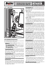
Страница 16: ...n not be moved one by one The push button E has one mechanically hold posi tion and controls the vertical translation of the lower bead breaking roll If pushed on its lower part it will control the downwards translation If pushed on its upper part it controls upward transla tion Keeping it pushed for more than one second translation carries on automatically until the arm reaches the stroke limit T...

Страница 17: ...CAPTURE 4 FI 7104 M007 4_B When tyre changer is started up the main screen page of the machine Home is displayed Coloured boxes with icons representing precise func tions are displayed in the bottom part of the main screen page and of each page afterwards described When the corresponding coloured push button on the rapid functions push button panel Fig 15 ref 10 or on the data entry push button pa...

Страница 18: ... procedure Return to Home screen page Selection up scroll Selection down scroll Selection confirmation Access to memory bank Exit from screen page Access to the following screen page Cyclic scroll of data to be person alized Values save in memory bank Activation of automatic procedure enabling of displayed operation Selection of upper tool device Selection of lower tool device Selection cancellati...

Страница 19: ...usly executed Use the arrows to select the required submenu Press key to confirm the selected choice Select Programs backup to save on the PC stored data eg memory bank on the USB key Press key to display the following machine screen page Once the presence of the USB key in the provided port has been verified press key to display the following screen page Press key to cancel the operation Press to...

Страница 20: ...er the analysis of such data Green coloured tyre soft program Blue coloured tyre standard program Red coloured tyre Run Fflat or UHP Ultra High Performance program 11 2 3 Read in of rim tyre combination in memory bank The computer is equipped with a memory bank where rim tyre combinations can be stored In order to enter a new rim tyre combination carry out the following operations from the main sc...

Страница 21: ...hould not correctly come into contact with the tyre rim use the push button Fig 14 ref D in order to diametrically translate them in the correct position 8 When wheel width measure acquisition ends press push button in order to confirm the measure then place the valve Fig B ref 1 next to the roll Fig B ref 2 When push button is pressed the machine is set to light transport mode and the following s...

Страница 22: ...Quick mode After wheel data entry the width acquisition can be performed as an alternative through a double click on the assent pedal IN AUTO AND MANUAL MODE THE FEELER PINS ARE DISABLED 11 2 4 Data save 1 Press key to save values in the memory bank 2 Further information can be entered in the screen page below in order to facilitate a future research Vehicle number plate Vehicle owner name Notes P...

Страница 23: ... machine automatic functioning in particular 1 Press key from Home page 2 Press key to enter the memory bank 1 2 3 All rim tyre combinations are displayed 3 Select the rim tyre combination present in the memory bank THE WHEEL PLATE NUMBER OR OWNER SEARCH FIELDS POSI TION 1 2 AND 3 IN THE SCREEN PAGE ABOVE CAN BE USED IN ORDER TO REDUCE TO A MINI MUM EXTENT THE SELECTION LISTS INSERT THE VALUES IN ...

Страница 24: ...lanatory pictures concerning the operation being executed will be displayed during demounting in particular Upper bead breaking roll Lower bead breaking roll Upper tool Lower tool At the end of tyre demounting operation the key will be displayed to indicate the end of automatic operations The tools and the bead breaking rolls keep their posi tion CAPTURE 4 CAPTURE 4 FI 7104 M007 4_B ...

Страница 25: ...tool and the upper bead breaking roll in the upper bead mounting position The valve positions itself before the entrainer inser tion point Attachments selection The type of attachment to be used to complete assembly can be used during this mounting phase A provided screen page allows the selection of the more suitable fixture to be used for the following operations before the mounting of the lower...

Страница 26: ...and bring the valve next to the upper bead breaking roll Press the assent pedal Fig 16 ref C twice to start a new tyre demounting mounting operation 11 3 Machine use in AUTO mode without PC management Press key from the screen page with the selection of the type of program to be used see Chap 11 2 3 Read in of rim tyre combination in memory bank the machine is set to AUTO without the cycle managem...

Страница 27: ...ontrolled pressure max 4 2 0 2 bar 60 PSI Version with tubeless inflation The inflation pedal has two functions The supply of air at a controlled pressure as in the previous version and a second function of a jet of air from the inflation nozzle to assist the beading in of the tyre Assent pedal C In AUTO mode from PC this pedal allows the ma chine to operate automatically When released the machine...

Страница 28: ...ONTACT THE MANUFACTURER WHICH WILL AUTHORIZE THE RETURN OF THE FAULTY SMART CARD IT WILL BE REPLACED WITH A WORKING ONE WITH THE SAME USB SERIAL NUMBER 13 0 USING THE MACHINE 13 1 Preliminary operations Preparing the wheel Remove the wheel balancing weights from both sides of the wheel Remove the valve stem and allow the tyre to com pletely deflate Establish from which side the tyre should be de m...

Страница 29: ...f 2 Fig 22 3 By removing the locking ring nut Fig 22 ref 1 from the activator support Fig 22 ref 2 the central threaded shaft Fig 23 ref 1 lifts auto matically until its maximum height AFTER A DEFAULT MANUFACTUR ING TIME THE THREADED SHAFT Fig 23 ref 1 RETURNS TO ITS OWN HOUSING IF THE LOCKING RING NUT HAS NOT BEEN IN SERTED YET IT IS POSSIBLE TO MAKE IT COME OUT AGAIN BY ACTIVATING MANUALLY THE A...

Страница 30: ...e end of the operations unlock the ring nut by loosening first the cone with the external levers and then moving the ring nut and the cone away from the rim with the small levers Place the locking ring nut onto its own activator support IN CASE THE PNEUMATIC SYS TEM FOR THE LIFTING OF THE THREADED CENTRAL SHAFT DOES NOT WORK IN ORDER TO CONTINUE WORKING UNTIL THE REPAIR HAS BEEN CAR RIED OUT LIFT ...

Страница 31: ...ion made of a transparent plastic material available on demand Fig 27 ref 1 We suggest a constant replacement of it and in any case if there are visible damages see Fig 27 Fig 27 1 13 3 Tyre bead breaking and demounting There are two different functioning modes in par ticular 1 Automatic from PC 2 Standard with manual controls 13 3 1 Tyre bead breaking and automatic demounting in AUTO mode from PC...

Страница 32: ...applied on both arms 7 Rotate the rim until the valve is positioned on the immediate right of the roll 8 For the upper edge bead breaking the instructions described above must be followed but using the push buttons related to the upper roll Fig 14 ref B and F UNTIL BOTH UPPER AND LOWER ROLLS DO NOT RE ENTER IS NOT POSSIBLE TO CARRY OUT A NEW DIAMETER ADJUSTMENT When both beads are broken the tyre ...

Страница 33: ...hes a vertical position related to the rim Fig 36 ref 1 rotate the mandrel so that the tyre enters the rim groove Keep on raising the tool until the bead is on the rim edge see Fig 35 MAKE SURE THAT THE TOOL IS ON DEMOUNTING POSITION FIG 35 BEFORE STARTING MANDREL ROTATION Fig 36 1 13 Rotate clockwise until the upper bead is completely disassembled see Fig 37 Fig 37 14 Lift the upper tool in order...

Страница 34: ...er can be used alternatively Lift the tool and go away from the working area 17 Lift the roll and the tyre just next to the rim edge see Fig 40 using the push button Fig 14 ref E Fig 40 18 Then move forward the roll through the provided control Fig 14 ref E so that it is inserted between the rim edge and the lower bead see Fig 41 Fig 41 19 Then rotate and complete bead disassembly see Fig 42 Fig 4...

Страница 35: ... tool Fig 43 ref 1 on the rim edge just next to the indicator reported in the tool Fig 43 1 3 Hook the bead on the tool Fig 44 ref 1 then rotate in clockwise direction until bead s complete assembly Remove the lower tool from the working area until the bead is completely released 1 Fig 44 4 Position the upper tool Fig 45 ref 1 just next to the rim edge Fig 45 1 5 Then position the upper bead on th...

Страница 36: ...e rim To conduct this operation carry out the following instructions Clamp the tyre between the bead breaker roll Turn the motor clockwise until the reference point on the tyre coincides with the reference point on the rim usually the valve see Fig 50 At the end of the operations the machine has stored the sizes width and rim diameter of the lastly used wheel When this mode is left press ESC key t...

Страница 37: ...ow the tyre to inflate faster and the bead to seat easier Connect the inflation terminal to the valve of the tyre TO IMPROVE THE EFFECTIVE NESS OF TUBELESS INFLATION SYSTEM ALWAYS LUBRICATE TYRE BEADS Press the bead blaster hose on the wheel rim as shown in Fig 51 Ensure the hose head is pressed in to activate the additional air jet THE NOZZLE SHOULD BE HORI ZONTAL FOR OPTIMAL PERFOR MANCE FIG 51 ...

Страница 38: ...anual intervention by the operator see Fig 52 1 PRESSURE REGULATOR DEPRESSURE RELEASE SEMI AUTOMATIC OILER AIR SUPPLY Fig 52 IN ORDER TO ENSURE A GOOD FUNCTIONING AND TO AVOID THE PRESENCE OF CONDENSATION IN THE AIR TREATMENT UNITS WITH SEMI AUTOMATIC DRAIN IT S NECESSARY TO MAKE SURE ABOUT THE CORRECT POSITION OF THE VALVE FIG 52 REF 1 PLACED UNDER THE CAP TO ACTIVATE A CORRECT DRAIN FUNCTION THE...

Страница 39: ...ACHINE DEVICES RESULTING FROM THE USE OF LUBRICANTS OTHER THAN THOSE RECOMMENDED IN THIS MANUAL WILL RELEASE THE MANUFACTURER FROM ANY LIABILITY 14 1 Neck adjustment In case of fulcrum type screws Fig 54 ref 2 with neck Fig 54 ref 3 fully beating onto bead breaking arm s guide Fig 54 ref 7 not on the adjusting plate Fig 54 ref 1 carry out neck adjustment procedure as described below Fig 54 KEY 1 A...

Страница 40: ...crew or screws Fig 56 ref 1 but without locking them just mak ing them approach setting a 0 1 0 2 mm play between neck Fig 56 ref 2 and adjusting plate Fig 56 ref 3 positioning nut Fig 56 ref 4 and letting it rest completely onto adjusting plate Fig 56 c Slacken lock nut Fig 57 ref 1 of adjusting dowel Fig 57 ref 2 Then slacken dowel Fig 57 ref 2 until neck Fig 57 ref 3 strikes onto arm Fig 57 ref...

Страница 41: ... order to reset 0 1 0 2 mm play between neck Fig 59 ref 2 and fulcrum type screws head Fig 59 ref 1 letting nut Fig 59 ref 3 rest completely onto adjusting plate Fig 59 ref 4 Fig 59 f Operate cylinder Fig 60 ref 1 supplying it with compressed air and make sure its stroke is in cluded between 5 10 mm Fig 60 g Blow off cylinder and make sure the arm Fig 61 ref 1 can slide freely in its guide Fig 61 ...

Страница 42: ... 1 5 kW Recommended electric supply single phase 200 265V 50 60 Hz Wheel maximum diameter 50 52 54 Wheel maximum width 15 Rim locking diameter 10 30 12 32 14 34 Bead breaking power per roll 10 bar 1200 kg Vertical bead breaker max opening 900mm Gear noise dBA 76 15 1 Weight Model without tubeless inflation 514 kg Model with tubeless inflation 520 kg CAPTURE 4 CAPTURE 4 FI 7104 M007 4_B ...

Страница 43: ...INSTRUCTION USE AND MAINTENANCE MANUAL GB Page 43 of 67 Fig 63 CAPTURE 4 CAPTURE 4 FI 7104 M007 4_B CAPTURE 4 FI ...

Страница 44: ...ows the meaning of the crossed dustbin symbol reported on the equipment indicates that the product must not be thrown among the undifferentiated rub bish that is to say together with the mixed urban waste but it has to be managed separately to let the WEEE go through special operations for their reuse or treatment in order to remove and dispose safely the waste that could be dangerous for the envi...

Страница 45: ...S TEILELISTE LISTE DES PIECES DETACHEES LISTA DE PIEZAS Pag 45 di 67 SCHEMA ELETTRICO 1 20 ELECTRICAL SCHEME 1 20 SCHALTPLAN 1 20 SCHEMA ELECTRIQUE 1 20 ESQUEMA ELECTRICO 1 20 Tavola N A Rev 3 710405530 CAPTURE 4 CAPTURE 4 FI 7104 M007 4_B ...

Страница 46: ...IECES DETACHEES LISTA DE PIEZAS Pag 46 di 67 SCHEMA ELETTRICO 2 20 ELECTRICAL SCHEME 2 20 SCHALTPLAN 2 20 SCHEMA ELECTRIQUE 2 20 ESQUEMA ELECTRICO 2 20 Tavola N A Rev 3 710405530 TOPOGRAFICO SCHEDA 18295 18295 TOPOGRAPHIC VIEW CAPTURE 4 CAPTURE 4 FI 7104 M007 4_B ...

Страница 47: ...S TEILELISTE LISTE DES PIECES DETACHEES LISTA DE PIEZAS Pag 47 di 67 SCHEMA ELETTRICO 3 20 ELECTRICAL SCHEME 3 20 SCHALTPLAN 3 20 SCHEMA ELECTRIQUE 3 20 ESQUEMA ELECTRICO 3 20 Tavola N A Rev 3 710405530 CAPTURE 4 CAPTURE 4 FI 7104 M007 4_B ...

Страница 48: ...S TEILELISTE LISTE DES PIECES DETACHEES LISTA DE PIEZAS Pag 48 di 67 SCHEMA ELETTRICO 4 20 ELECTRICAL SCHEME 4 20 SCHALTPLAN 4 20 SCHEMA ELECTRIQUE 4 20 ESQUEMA ELECTRICO 4 20 Tavola N A Rev 3 710405530 CAPTURE 4 CAPTURE 4 FI 7104 M007 4_B ...

Страница 49: ...S TEILELISTE LISTE DES PIECES DETACHEES LISTA DE PIEZAS Pag 49 di 67 SCHEMA ELETTRICO 5 20 ELECTRICAL SCHEME 5 20 SCHALTPLAN 5 20 SCHEMA ELECTRIQUE 5 20 ESQUEMA ELECTRICO 5 20 Tavola N A Rev 3 710405530 CAPTURE 4 CAPTURE 4 FI 7104 M007 4_B ...

Страница 50: ...S TEILELISTE LISTE DES PIECES DETACHEES LISTA DE PIEZAS Pag 50 di 67 SCHEMA ELETTRICO 6 20 ELECTRICAL SCHEME 6 20 SCHALTPLAN 6 20 SCHEMA ELECTRIQUE 6 20 ESQUEMA ELECTRICO 6 20 Tavola N A Rev 3 710405530 CAPTURE 4 CAPTURE 4 FI 7104 M007 4_B ...

Страница 51: ...S TEILELISTE LISTE DES PIECES DETACHEES LISTA DE PIEZAS Pag 51 di 67 SCHEMA ELETTRICO 7 20 ELECTRICAL SCHEME 7 20 SCHALTPLAN 7 20 SCHEMA ELECTRIQUE 7 20 ESQUEMA ELECTRICO 7 20 Tavola N A Rev 3 710405530 CAPTURE 4 CAPTURE 4 FI 7104 M007 4_B ...

Страница 52: ...S TEILELISTE LISTE DES PIECES DETACHEES LISTA DE PIEZAS Pag 52 di 67 SCHEMA ELETTRICO 8 20 ELECTRICAL SCHEME 8 20 SCHALTPLAN 8 20 SCHEMA ELECTRIQUE 8 20 ESQUEMA ELECTRICO 8 20 Tavola N A Rev 3 710405530 CAPTURE 4 CAPTURE 4 FI 7104 M007 4_B ...

Страница 53: ...S TEILELISTE LISTE DES PIECES DETACHEES LISTA DE PIEZAS Pag 53 di 67 SCHEMA ELETTRICO 9 20 ELECTRICAL SCHEME 9 20 SCHALTPLAN 9 20 SCHEMA ELECTRIQUE 9 20 ESQUEMA ELECTRICO 9 20 Tavola N A Rev 3 710405530 CAPTURE 4 CAPTURE 4 FI 7104 M007 4_B ...

Страница 54: ...te rispetto al senso di avanzamento dell asse devono essere scambiati tra loro i fili giallo e verde ASSEGNAZIONE CONNETTORI JP1 1 GND 2 3 24V 20A ALIMENTAZIONE JP2 1 Rit 3B 1B 2B 8B 2 3B EV giu V1 3 1B EV giu V2 4 2B EV giu V3 5 8B EV giu V4 6 USCITE JP3 1 Rit 3A 1A 2A 8A Cavallottare filo 8A su JP6 1 2 3A EV su V1 3 1A EV su V2 4 2A EV su V3 5 8A EV su V4 6 USCITE JP4 1 MARRONE GRIGIO RITORNO 11...

Страница 55: ...L SCHEME 11 20 SCHALTPLAN 11 20 SCHEMA ELECTRIQUE 11 20 ESQUEMA ELECTRICO 11 20 Tavola N A Rev 3 710405530 BROWN GRAY RETURN 11A 11B 11A 11B SV FORWARD V11 SV BACK V11 10A 10B SV FORWARD V10 SV BACK V10 Rit 6A 6B 7 8A UPPER FEELER PIN LOWER FEELER PIN MICRO 10A 10B 710465530 GREEN YELLOW 710465520 GREEN CAPTURE 4 CAPTURE 4 FI 7104 M007 4_B ...

Страница 56: ...u V1 SB7 7 3 1n Tasto su V2 SB1 1 4 3n Tasto su V3 SB3 3 5 9n Tasto su V4 SB10 9 6 8n Tasto giu V1 SB8 8 7 2n Tasto giu V2 SB2 2 8 4n Tasto giu V3 SB4 4 9 11n Tasto giu V4 SB11 11 JP23 1 24V ROSA 18945 PROXIMITY COMUN E MICRO C1 C2 2 GIALLO 18945 PROXY SX 3 VERDE 18945 PROXY DX 4 12n Tasto MAN AUTO 5 NC2 MARRONE 18885 Sens L GIALLO Rit JP21 1 6 NC1 BIANCO 18885 SENS H VERDE Rit JP21 1 7 VERDE Cod ...

Страница 57: ...7 di 67 SCHEMA ELETTRICO 13 20 ELECTRICAL SCHEME 13 20 SCHALTPLAN 13 20 SCHEMA ELECTRIQUE 13 20 ESQUEMA ELECTRICO 13 20 Tavola N A Rev 3 710405530 710465530 710465520 GRAY 710465530 GRAY 710465520 WHITE 710465530 19193 BLUE 19193 BLUE 19193 BLUE 19193 BLUE A A n n CAPTURE 4 CAPTURE 4 FI 7104 M007 4_B ...

Страница 58: ...TEILELISTE LISTE DES PIECES DETACHEES LISTA DE PIEZAS Pag 58 di 67 SCHEMA ELETTRICO 14 20 ELECTRICAL SCHEME 14 20 SCHALTPLAN 14 20 SCHEMA ELECTRIQUE 14 20 ESQUEMA ELECTRICO 14 20 Tavola N A Rev 3 710405530 CAPTURE 4 CAPTURE 4 FI 7104 M007 4_B ...

Страница 59: ...TEILELISTE LISTE DES PIECES DETACHEES LISTA DE PIEZAS Pag 59 di 67 SCHEMA ELETTRICO 15 20 ELECTRICAL SCHEME 15 20 SCHALTPLAN 15 20 SCHEMA ELECTRIQUE 15 20 ESQUEMA ELECTRICO 15 20 Tavola N A Rev 3 710405530 CAPTURE 4 CAPTURE 4 FI 7104 M007 4_B ...

Страница 60: ...TEILELISTE LISTE DES PIECES DETACHEES LISTA DE PIEZAS Pag 60 di 67 SCHEMA ELETTRICO 16 20 ELECTRICAL SCHEME 16 20 SCHALTPLAN 16 20 SCHEMA ELECTRIQUE 16 20 ESQUEMA ELECTRICO 16 20 Tavola N A Rev 3 710405530 CAPTURE 4 CAPTURE 4 FI 7104 M007 4_B ...

Страница 61: ...ILELISTE LISTE DES PIECES DETACHEES LISTA DE PIEZAS Pag 61 di 67 SCHEMA ELETTRICO 17 20 ELECTRICAL SCHEME 17 20 SCHALTPLAN 17 20 SCHEMA ELECTRIQUE 17 20 ESQUEMA ELECTRICO 17 20 Tavola N A Rev 3 710405530 K3 CAPTURE 4 CAPTURE 4 FI 7104 M007 4_B ...

Страница 62: ...TEILELISTE LISTE DES PIECES DETACHEES LISTA DE PIEZAS Pag 62 di 67 SCHEMA ELETTRICO 18 20 ELECTRICAL SCHEME 18 20 SCHALTPLAN 18 20 SCHEMA ELECTRIQUE 18 20 ESQUEMA ELECTRICO 18 20 Tavola N A Rev 3 710405530 CAPTURE 4 CAPTURE 4 FI 7104 M007 4_B ...

Страница 63: ...T BALANCING PUSHBUTTON PUSHBUTTON UNIPOLAR LEVER SWITCH RED MUSHROOM HEAD PUSHBUTTON FEEDER CABLE PRESS SENSOR NOT WATERPROOF CONTACTORS ELECTRIC MOTOR REMOV PIN CASE MOT 71 INVERTER 10 3x38 32A 690V 2 POLES SECTIONABLE 10 3x38 25A 500V aM DELAYED ACTION SE32 40A GIOVENZANA SE3210F28 2 POLES BL PADL HOLDER GIOVENZANA A 012 0001 1 TERM 2mmq ART CBD 2 CABUR CB110 TERM G V 4mmq ART TEO 4 CABUR T0430 ...

Страница 64: ... LISTA DE PIEZAS Pag 64 di 67 SCHEMA ELETTRICO 20 20 ELECTRICAL SCHEME 20 20 SCHALTPLAN 20 20 SCHEMA ELECTRIQUE 20 20 ESQUEMA ELECTRICO 20 20 Tavola N A Rev 3 710405530 N B COLLEGARE IL MICRO SU CONTATTO NA NB CONNECT THE MICRO ON NO CONTACT CAPTURE 4 CAPTURE 4 FI 7104 M007 4_B ...

Страница 65: ...PONENTS TEILELISTE LISTE DES PIECES DETACHEES LISTA DE PIEZAS Pag 65 di 67 Tavola N B Rev 2 710405130 SCHEMA PNEUMATICO PNEUMATIC CIRCUIT DIAGRAM PNEUMATIKPLAN SCHEMA PNEUMATIQUE ESQUEMA NEUMATICO CAPTURE 4 CAPTURE 4 FI 7104 M007 4_B ...

Страница 66: ... L 1600 Tubo rilsan 6x4 negro L 1600 18 317006 Tubo rilsan 6x4 nero L 50 6x4 black rilsan pipe L 50 Rilsan Schlauch 6x4 schwarz L 50 Tuyau rilsan 6x4 noir L 50 Tubo rilsan 6x4 negro L 50 19 317006 Tubo rilsan 6x4 nero L 1850 6x4 black rilsan pipe L 1850 Rilsan Schlauch 6x4 schwarz L 1850 Tuyau rilsan 6x4 noir L 1850 Tubo rilsan 6x4 negro L 1850 20 317006 Tubo rilsan 6x4 nero L 650 6x4 black rilsan...

Страница 67: ...e L 1200 Rilsanschlauch 10x8 schwarz L 1200 Tuyau rilsan 10x8 noir L 1200 Tubo rilsan 10x8 negro L 1200 56 Lubrificatore Lubricator Schmierer Graisseur Lubrificador 57 317009 Tubo rilsan 8x6 blu L 1350 8x6 blue rilsan pipe L 1350 Rilsan Schlauch 8x6 blau L 1350 Tuyau rilsan 8x6 bleu L 1350 Tubo rilsan 8x6 azul L 1350 58 325181 Raccordo a V8 V8 union V Verbindung 8 Raccord à V8 Enlace a V8 59 31700...

Страница 68: ...OF PARTS TO BE REPLACED THE REPLACEMENT MUST BE CARRIED OUT PROFESSIONALLY QUALIFIED PER SONNEL DIE ZEICHNUNGEN DIENEN NUR ZUR IDENTIFIZIERUNG DER ERSATZTEILE DIE ERSETZUNG MUSS DURCH QUALIFIZIERTES PERSONAL ERFOLGEN LES DESSINS NE SERVENT QU À L IDENTIFICATION DES PIÈCES À REMPLACER LE REMPLACEMENT DOIT ÊTRE EFFECTUÉ PAR UN PERSONNE PROFESSIONNEL LEMENT QUALIFIÉ LOS DIBUJOS EN DESPIECE SIRVEN ÚNI...

Страница 69: ...SUPÉRIEUR GRUPO ENCODER UTENSILIO SUPERIOR Tavola N 11 Rev 1___ 710490820 18 COLONNA CON INSERTI COLUMN WITH INSERTS SÄULE MIT EINSATZEN COLONNE AVEC RENFORTS COLUMNA CON INSERCIONES Tavola N 12 Rev 2___ 710491570 19 GRUPPO BASAMENTO DRIVE BASE UNIT UNTERGESTELLSATZ GROUPE BÂTI GRUPO BASE Tavola N 13 Rev 2___ 710491560 20 GRUPPO AUTOCENTRANTE SELFCENTERING CHUCK UNIT AUTOZENTRIERESATZ GROUPE AUTOC...

Страница 70: ... MTG CAJA FICHA ADICIONAL Tavola N 27 Rev 2___ 710491181 34 GRUPPO CHIUSURA CON IMPIANTO ELETTRICO CLOSING UNIT WITH ELECTRIC SYSTEM VERSCHLUSSSATZ MIT MIT ELEKTROANLAGE GROUPE DE FERMETURE AVEC SYSTÈME ÉLECTRIQUE GRUPO DE CIERRE CON SISTEMA ELÉCTRICO Tavola N 28 Rev 2___ 710403090 35 MTG CASSETTA ELETTRICA ELECTRICAL BOX MTG MTG ELEKTRISCHEKISTE MTG BOITER ÉLECTRIQUE MTG CAJITA ELECTRICA Tavola N...

Страница 71: ...NTI LIST OF COMPONENTS TEILELISTE LISTE DES PIECES DETACHEES LISTA DE PIEZAS Pag 4 di 38 ASSIEME GENERALE MAIN ASSEMBLY GENERALSATZ ASSEMBLAGE GENERAL JUNTO GENERAL Tavola N 1 Rev 3 7104 R007 3_B CAPTURE 4 CAPTURE 4 FI ...

Страница 72: ...Rev 3 2 710491161 3 710490440 4 710490450 5 710191280 6 710491020 7 710491030 8 710191360 9 710191370 10 710490670 11 710490820 12 710491570 13 710491560 14 710490610 15 710490690 16 710490401 17 710490730 18 140990371 19 B4127300 20 710490621 21 710490800 22 710490810 23 710490832 24 710090920 25 710490970 26 710403070 27 710491181 28 710403090 7104 R007 3_B CAPTURE 4 CAPTURE 4 FI CAPTURE 4 CAPTU...

Страница 73: ...vola N 1 Rev 3 29 710491520 30 710190830 31 790090180 B0223000 32 B1157000 33 10197 34 19706 35 203172 36 206012 37 206019 38 228211 39 272019 40 710013421 41 710411810 42 710411820 43 710413440 44 710416630 45 710416610 46 710416600 47 710416620 48 710414451 49 710414470 50 710416040 51 710490750 52 272188 53 710414130 54 710491210 55 7104 R007 3_B CAPTURE 4 CAPTURE 4 FI CAPTURE 4 CAPTURE 4 FI ...

Страница 74: ...O GENERAL Tavola N 1 Rev 3 710416650 56 B3163000 57 220053 58 710491200 59 710416640 60 239017 61 206207 62 B0171000 63 399275 64 399284 65 325191 66 B0178000 67 B1949000 68 B5717000 69 B9451000 70 18964 71 20052 72 325086 73 325186 74 710114870 75 272172 76 710011710 77 203035 78 228501 79 B1695000 80 B9474000 81 599090 82 7104 R007 3_B CAPTURE 4 CAPTURE 4 FI CAPTURE 4 CAPTURE 4 FI ...

Страница 75: ...S LISTA DE PIEZAS Pag 8 di 38 Cod Pos Tav 599442 83 599561 84 599562 85 599563 86 999105 87 325181 88 325054 89 G1000A152 90 ASSIEME GENERALE MAIN ASSEMBLY GENERALSATZ ASSEMBLAGE GENERAL JUNTO GENERAL Tavola N 1 Rev 3 7104 R007 3_B CAPTURE 4 CAPTURE 4 FI CAPTURE 4 CAPTURE 4 FI ...

Страница 76: ... COMPONENTS TEILELISTE LISTE DES PIECES DETACHEES LISTA DE PIEZAS Pag 9 di 38 GRUPPO COLONNA COLUMN UNIT SÄULESATZ GROUPE COLONNE GRUPO COLUMNA Tavola N 2 Rev 2 710491161 7104 R007 3_B CAPTURE 4 CAPTURE 4 FI CAPTURE 4 CAPTURE 4 FI ...

Страница 77: ...ISTE DES PIECES DETACHEES LISTA DE PIEZAS Pag 10 di 38 GRUPPO ENCODER UTENSILI TOOLS ENCODER UNIT WERKZEUGENENCODERSATZ GROUPE ENCODER OUTILES GRUPO ENCODER UTENSILIOS Tavola N 3 Rev 2 710490440 7104 R007 3_B CAPTURE 4 CAPTURE 4 FI CAPTURE 4 CAPTURE 4 FI ...

Страница 78: ...IECES DETACHEES LISTA DE PIEZAS Pag 11 di 38 GRUPPO ENCODER STALLONATORI BEAD BREAKING ENCODER UNIT ABDRÜCKENCODERSATZ GROUPE ENCODER DÉCOLLE TALONS GRUPO ENCODER DESTALONADORES Tavola N 4 Rev 2 710490450 7104 R007 3_B CAPTURE 4 CAPTURE 4 FI CAPTURE 4 CAPTURE 4 FI ...

Страница 79: ... Tavola N 5 Rev 2 710191280 16 15 8 7 6 6 3 21 20 20 21 19 18 29 25 30 32 31 26 26 34 27 27 28 24 22 23 23 33 33 35 16 15 4 1 5 14 13 9 2 17 10 11 9 3 12 GRUPPO SUPPORTO BRACCIO ARM SUPPORT UNIT ARMTRÄGERSATZ GROUPE SUPPORT BRAS GRUPO SOPORTE BRAZO 7104 R007 3_B CAPTURE 4 CAPTURE 4 FI CAPTURE 4 CAPTURE 4 FI ...

Страница 80: ...CES DETACHEES LISTA DE PIEZAS Pag 13 di 38 GRUPPO SUPPORTO BRACCIO SUPERIORE UPPER ARM SUPPORT UNIT OBERER ARMTRÄGERSATZ GROUPE SUPPORT BRAS SUPÉRIEUR GRUPO SOPORTE BRAZO SUPERIOR Tavola N 6 Rev 3 710491020 7104 R007 3_B CAPTURE 4 CAPTURE 4 FI CAPTURE 4 CAPTURE 4 FI ...

Страница 81: ...ZAS Pag 14 di 38 GRUPPO SUPPORTO BRACCIO INFERIORE LOWER ARM SUPPORT UNIT UNTERER ARMTRÄGERSATZ GROUPE SUPPORT BRAS INFÉRIEUR GRUPO SOPORTE BRAZO INFERIOR Tavola N 7 Rev 2 710491030 1 2 3 4 5 6 7 8 9 10 10 11 12 13 14 15 16 17 18 19 7104 R007 3_B CAPTURE 4 CAPTURE 4 FI CAPTURE 4 CAPTURE 4 FI ...

Страница 82: ... UPPER FEELER PIN GUIDE UNIT FÜHRUNGSATZ OBEREN ABTASTERS GROUPE GUIDE TÂTEUR SUPÉRIEUR GRUPO GUÍA PALPADOR SUPERIOR Tavola N 8 Rev 1 710191360 1 1 1 1 2 3 4 4 5 5 6 6 7 8 9 10 10 10 11 12 12 13 14 15 16 17 18 18 18 18 18 19 19 19 19 20 21 22 23 24 25 26 26 27 28 29 30 32 33 31 34 7104 R007 3_B CAPTURE 4 CAPTURE 4 FI CAPTURE 4 CAPTURE 4 FI ...

Страница 83: ...UIDA TASTATORE INFERIORE LOWER FEELER PIN GUIDE UNIT FÜHRUNGSATZ UNTEREN ABTASTERS GROUPE GUIDE TÂTEUR INFÉRIEUR SUPÉRIEUR GRUPO GUÍA PALPADOR INFERIOR Tavola N 9 Rev 2 710191370 1 1 1 1 2 3 4 5 5 6 6 7 8 9 10 10 11 12 13 14 14 15 16 17 17 18 20 19 21 22 23 7104 R007 3_B CAPTURE 4 CAPTURE 4 FI CAPTURE 4 CAPTURE 4 FI ...

Страница 84: ...CHEES LISTA DE PIEZAS Pag 17 di 38 GRUPPO ENCODER UTENSILE SUPERIORE UPPER TOOL ENCODER UNIT OBERER WERKZEUGENENCODERSATZ GROUPE ENCODER OUTIL SUPÉRIEUR GRUPO ENCODER UTENSILIO SUPERIOR Tavola N 10 Rev 2 710490670 7104 R007 3_B CAPTURE 4 CAPTURE 4 FI CAPTURE 4 CAPTURE 4 FI ...

Страница 85: ... 18 di 38 COLONNA CON INSERTI COLUMN WITH INSERTS SÄULE MIT EINSATZEN COLONNE AVEC RENFORTS COLUMNA CON INSERCIONES Tavola N 11 Rev 1 710490820 1 2 2 4 4 4 4 4 4 5 5 6 7 7 7 10 11 11 12 12 12 12 12 12 14 15 16 17 20 21 22 19 18 18 13 9 8 3 7104 R007 3_B CAPTURE 4 CAPTURE 4 FI CAPTURE 4 CAPTURE 4 FI ...

Страница 86: ...ONENTS TEILELISTE LISTE DES PIECES DETACHEES LISTA DE PIEZAS Pag 19 di 38 GRUPPO BASAMENTO DRIVE BASE UNIT UNTERGESTELLSATZ GROUPE BÂTI GRUPO BASE Tavola N 12 Rev 2 710491570 7104 R007 3_B CAPTURE 4 CAPTURE 4 FI CAPTURE 4 CAPTURE 4 FI ...

Страница 87: ...TE LISTE DES PIECES DETACHEES LISTA DE PIEZAS Pag 20 di 38 GRUPPO AUTOCENTRANTE SELFCENTERING CHUCK UNIT AUTOZENTRIERESATZ GROUPE AUTOCENTREUR GRUPO AUTOCENTRANTE Tavola N 13 Rev 2 710491560 7104 R007 3_B CAPTURE 4 CAPTURE 4 FI CAPTURE 4 CAPTURE 4 FI ...

Страница 88: ... DES PIECES DETACHEES LISTA DE PIEZAS Pag 21 di 38 GRUPPO MOTORE INVERTER INVERTER MOTOR UNIT FREQUENUMFORMER DES MOTORSATZES GROUPE MOTEUR VARIATEUR GRUPO MOTOR INVERSOR Tavola N 14 Rev 2 710490610 7104 R007 3_B CAPTURE 4 CAPTURE 4 FI CAPTURE 4 CAPTURE 4 FI ...

Страница 89: ...i 38 GRUPPO COFANO CON PEDALIERE CASING UNIT WITH PEDALBOARDS HAUBESATZ MIT PEDALLEISTE GROUPE COFFRE AVEC PÉDALES DE DIRECTION GRUPO CAPOT CON PEDALERAS Tavola N 15 Rev 2 710490690 4 3 3 1 5 6 6 7 8 9 10 11 12 13 14 15 16 2 3 3 3 3 14 15 18 17 7104 R007 3_B CAPTURE 4 CAPTURE 4 FI CAPTURE 4 CAPTURE 4 FI ...

Страница 90: ...IECES DETACHEES LISTA DE PIEZAS Pag 23 di 38 PEDALIERA PER INVERTER PEDALBOARD FOR INVERTER PEDALLEISTE FÜR INVERTER PÉDALES DE DIRECTION POUR INVERSEUR PEDALERA PARA INVERTER Tavola N 16 Rev 0 710490401 7104 R007 3_B CAPTURE 4 CAPTURE 4 FI CAPTURE 4 CAPTURE 4 FI ...

Страница 91: ... DETACHEES LISTA DE PIEZAS Pag 24 di 38 GRUPPO PEDALIERA CONSENSO ASSENT PEDALBOARD UNIT SATZ VON FREIGABEPEDALLEISTE GROUPE PÉDALES DE DIRECTIO CONSENTEMENT GRUPO PEDALERA CONSENSO Tavola N 17 Rev 0 710490730 7104 R007 3_B CAPTURE 4 CAPTURE 4 FI CAPTURE 4 CAPTURE 4 FI ...

Страница 92: ...8 GRUPPO PEDALIERA GONFIATUBELESS TUBELESS INFLATION PEDALBOARD PEDALERIE TUBELESS PÉDALES DE DIRECTION DE GONFLAGE TUBELESS PEDALERA DE INFLADO TUBELESS Tavola N 18 Rev 1 140990371 1 2 3 4 5 5 6 6 6 7 8 9 10 10 11 12 13 14 4 15 15 4 9 16 16 17 18 7104 R007 3_B CAPTURE 4 CAPTURE 4 FI CAPTURE 4 CAPTURE 4 FI ...

Страница 93: ...ES DETACHEES LISTA DE PIEZAS Pag 26 di 38 PEDALIERA DI GONFIAGGIO INFLATION PEDALBOARD PEDALERIE PÉDALES DE DIRECTION DE GONFLAGE PEDALERA DE INFLADO Tavola N 19 Rev 1 B4127300 1 2 3 4 6 5 5 6 6 7 8 9 10 11 7104 R007 3_B CAPTURE 4 CAPTURE 4 FI CAPTURE 4 CAPTURE 4 FI ...

Страница 94: ...S Pag 27 di 38 GRUPPO FRONTALE CON PULSANTI FRONT UNIT WITH PUSHBUTTONS FRONTSATZ MIT KNÖPFE GROUPE FRONTAL AVEC POUSSOIRS GRUPO FRONTAL CON PULASADORES Tavola N 20 Rev 2 710490621 1 2 2 3 4 5 5 6 6 7 8 9 9 10 11 12 13 14 15 16 17 18 7104 R007 3_B CAPTURE 4 CAPTURE 4 FI CAPTURE 4 CAPTURE 4 FI ...

Страница 95: ...MPONENTS TEILELISTE LISTE DES PIECES DETACHEES LISTA DE PIEZAS Pag 28 di 38 GRUPPO MONITOR MONITOR UNIT MONITORSATZ GROUPE MONITEUR GRUPO MONITOR Tavola N 21 Rev 2 710490800 7104 R007 3_B CAPTURE 4 CAPTURE 4 FI CAPTURE 4 CAPTURE 4 FI ...

Страница 96: ...PONENTS TEILELISTE LISTE DES PIECES DETACHEES LISTA DE PIEZAS Pag 29 di 38 GRUPPO TASTIERA KEYBOARD UNIT TASTATURSATZ GROUPE CLAVIER GRUPO TECLADO Tavola N 22 Rev 0 710490810 7104 R007 3_B CAPTURE 4 CAPTURE 4 FI CAPTURE 4 CAPTURE 4 FI ...

Страница 97: ...COMPONENTS TEILELISTE LISTE DES PIECES DETACHEES LISTA DE PIEZAS Pag 30 di 38 GRUPPO BOX PC BOX PC UNIT BOX PC SATZ GROUPE BOX PC GRUPO BOX PC Tavola N 23 Rev 2 710490832 7104 R007 3_B CAPTURE 4 CAPTURE 4 FI CAPTURE 4 CAPTURE 4 FI ...

Страница 98: ...ES DETACHEES LISTA DE PIEZAS Pag 31 di 38 GRUPPO TRATTAMENTO ARIA AIR TREATMENT UNIT AUFBEREITUNGLUFTSATZ GROUPE TRAITEMENT AIR GRUPO TRATAMIENTO AIR Tavola N 24 Rev 2 710090920 1 2 3 4 5 6 7 8 2 9 10 11 12 7104 R007 3_B CAPTURE 4 CAPTURE 4 FI CAPTURE 4 CAPTURE 4 FI ...

Страница 99: ...IECES DETACHEES LISTA DE PIEZAS Pag 32 di 38 GRUPPO STAFFA SOLLEVAMENTO LIFTING DEVICE BRACKET UNIT ABZIGVORRICHTUNGBÜGELSATZ GROUPE BRIDE SOULÈVEMENT GRUPO BRIDA LEVANTAMIENTO Tavola N 25 Rev 0 710490970 7104 R007 3_B CAPTURE 4 CAPTURE 4 FI CAPTURE 4 CAPTURE 4 FI ...

Страница 100: ...S LISTA DE PIEZAS Pag 33 di 38 MTG SCATOLA SCHEDA AGGIUNTIVA MTG BOX ADDITIONAL CARD MTG KASTEN ZUSATZKARTE MTG BOÎTE CARTE ADDITIONNEL MTG CAJA FICHA ADICIONAL Tavola N 26 Rev 2 710403070 1 2 2 3 3 4 5 6 6 7 8 9 10 11 7104 R007 3_B CAPTURE 4 CAPTURE 4 FI CAPTURE 4 CAPTURE 4 FI ...

Страница 101: ...S Pag 34 di 38 GRUPPO CHIUSURA CON IMPIANTO ELETTRICO CLOSING UNIT WITH ELECTRIC SYSTEM VERSCHLUSSSATZ MIT MIT ELEKTROANLAGE GROUPE DE FERMETURE AVEC SYSTÈME ÉLECTRIQUE GRUPO DE CIERRE CON SISTEMA ELÉCTRICO Tavola N 27 Rev 2 710491181 7104 R007 3_B CAPTURE 4 CAPTURE 4 FI CAPTURE 4 CAPTURE 4 FI ...

Страница 102: ... LISTA DE PIEZAS Pag 35 di 38 MTG CASSETTA ELETTRICA ELECTRICAL BOX MTG MTG ELEKTRISCHEKISTE MTG BOITER ÉLECTRIQUE MTG CAJITA ELECTRICA Tavola N 28 Rev 2 710403090 1 15 7 4 12 6 8 9 4 9 4 11 5 14 8 10 11 11 11 2 13 4 43 7104 R007 3_B CAPTURE 4 CAPTURE 4 FI CAPTURE 4 CAPTURE 4 FI ...

Страница 103: ...TS TEILELISTE LISTE DES PIECES DETACHEES LISTA DE PIEZAS Pag 36 di 38 GRUPPO ATTIVATORE ACTIVATOR UNIT AKTIVATORSATZ GROUPE ACTIVATEUR GRUPO ACTIVADOR Tavola N 29 Rev 2 710491520 7104 R007 3_B CAPTURE 4 CAPTURE 4 FI CAPTURE 4 CAPTURE 4 FI ...

Страница 104: ...ES LISTA DE PIEZAS Pag 37 di 38 Tavola N 30 Rev 2 710190830 GRUPPO SPINGITALLONE CON GUARDIA BEAD DEPRESSOR UNIT WITH GUIDE WULSTNIEDERHALTERSSATZ MIT FÜHRUNG GROUPE POUSSE TALONS AVEC GUIDE GRUPO EMPUJATALÓN CON GUÍA 7104 R007 3_B CAPTURE 4 CAPTURE 4 FI CAPTURE 4 CAPTURE 4 FI ...

Страница 105: ...S TEILELISTE LISTE DES PIECES DETACHEES LISTA DE PIEZAS Pag 38 di 38 GRUPPO GONFIAGGIO INFLATION GROUP AUFPUMPENSATZ GROUPE DE GONFLAGE GRUPO DE INFLADO Tavola N 31 Rev 2 790090180 7104 R007 3_B CAPTURE 4 CAPTURE 4 FI CAPTURE 4 CAPTURE 4 FI ...

Отзывы: