INSTRUCTION, USE AND
MAINTENANCE MANUAL
GB
Page 15 of 67
10.2 Lighting
The machine does not require its own lighting for
normal working operations. However, it must be used
in an adequately lit environment.
In case of poor lighting use lamps having total power
of 800/1200 Watt.
10.3 Working area modification
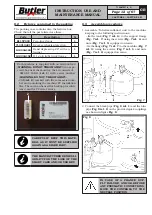
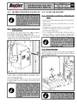
After the delivery, the machine is prearranged to op-
erate on wheel of 50” maximum diameter and a rim
diameter (10” - 30”). It’s also possible to move the tools
column to enlarge the working area from 52” (with rim
diameter of 12” - 32”) and up to 54” (with rim diameter
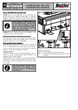
of 14” - 34”) (see
Fig. 12
)
Fig. 12
The column is moved by unloosing the fixing screws of
the base (
Fig. 12 ref. A
) to the column (
Fig. 12 ref. B
)
and by sliding the base (
Fig. 12 ref. A
) itself into the
proper slots until the required measure.
MAKE SURE THAT THE TYRE-
CHANGER COLUMN IS STABLE:
USE A CABLE HELD BY A HOIST
AND HOOK IT TO THE APPROPRI-
ATE LIFTING TRAVERSE (FIG. 13
REF. 7).
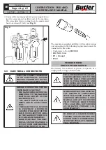
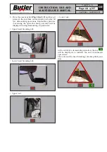
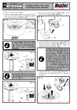
1. Remove the lateral guards (
Fig. 13 ref. 1-2
) of the
machine.
2. Unscrew the screws (
Fig. 13 ref. 3
) and the nuts
near the central slots (
Fig. 13 ref. 4
) paying atten-
tion not to remove the nuts from the proper screws.
3. Remove the six remaining screws (
Fig. 13 ref. 5
).
4. Move the base (
Fig. 13 ref. 6
) into the required
position (to 52” or 54”) and if necessary, use a lifting
device (
Fig. 13 ref. 7
).
5. Lock the base three screws (
Fig. 13 ref. 3
) with a
couple of 80 Nm.
6. Place six screws (
Fig. 13 ref. 5
) previously removed
and lock them on the bases side with a couple of
80 Nm.
7. Assemble again the lateral guards (
Fig. 13 ref. 1-2
)
of the machine.
AFTER THE ASSEMBLY, CHECK
THE CORRECT POSITION OF THE
TOOLS. LOCK THE RIM ON THE
MANDREL CENTRE. WITH THE
LOWER BEAD BREAKER ARM,
CHECK THAT THE DISTANCE BE-
TWEEN THE ROLL AND THE RIM
EDGES (UPPER AND LOWER) IS
ALMOST THE SAME. REPEAT ALL
THE PROCEDURES STARTING
FROM POINT 1 IF THE DISTANCE
IS NOT THE SAME.
Fig. 13
CAPTURE 4 - CAPTURE 4 FI
7104-M007-4_B


