


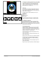


LCD Screen (Fig 12.0).
A full color,
back-lit
LCD screen that can show Omni2
configuration details and operating information to the
installer and user. Further details of actual displays are given
in the LCD Screen Details section and throughout this
manual.
Power
Button (Fig 12.0).
The Power button provides a complete power-down of the
control system electronics. In addition to the button mounted
on the Display Section, there is facility for an optional,
externally-mounted user switch on the Input Section. Refer to
the External On/Off Switch Jack paragraph for further details.
Settings Button (Fig 12.0).
The Settings button launches the Settings Menu screen.
Refer to the Settings Menu section for further details
Mode Button (Fig 12.0).
The Mode button allows you to change between the available
Modes.
Profile Button (Fig 12.0).
The Profile button allows you to change between the
available Drive Profiles.
Navigation Buttons (Fig 12.0).
The array of 4 Navigation buttons allows the function screens
to be navigated
.
- / + Buttons (Fig 12.0).
These buttons make adjustments to highlighted parameters
.
Display / Input Section Connector (Fig 12.
0
).
This connector is used to link the Display Section to the Input
Section.
Use only supplied cable.
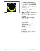
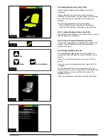
Charger Socket (Fig 12.1).
This 3-pin socket can be used to charge the power chair
batteries and, dependent on system programming, to lock
the power chair. For details of battery charging, refer
to the
supplied battery charger owner's
manual.
USB Port (Fig 12.1).
This ‘Type A’ USB socket can be used to charge devices
such as mobile phones.
Communications Connector (Fig 12.1).
This connector links the
Omni2
to the R-Net system.
9-way D-type Specialty Input Device (SID) Connectors,
(Fig 12.
1
).
These provide connections to analogue or digital SIDs. There
is a facility to detect if a mating connector is in place; and
provision of a low current 12V supply.
User
Switch
Jacks (Fig 12.
1
).
There are two
1/8" (3.5mm)
mono jacks
which provide
connection
to the User Switches. Full details of
User Switches can be found in the Connection of SIDs
section.
External On/Off Switch
Jack
(Fig 12.
1
).
This is a
1/8" (3.5mm)
mono jack
which provides connection
to a user operated On/Off button. This connection is optional
and the
Omni2
will function normally without it.
Sip and Puff Input (Fig 12.
1
).
This input will accept a 1/8"
(3.5mm)
pipe
/ tube
connected to
a Sip and Puff mouthpiece.
Display / Input Section Connector (Fig 12.1).
This connector is used to link the Input Section to the Display
Section.
Use only supplied cable.
CAUTION
!
CAUTION
!
249044 Rev. A
36
R-Net Control System w/Omni2
Содержание R-net
Страница 1: ...Instructions for Use R Net Control System R Net Controls P N 249044 Rev A ...
Страница 7: ...LED and CJSM1 249044 Rev A 7 R Net Control System w Omni2 ...
Страница 34: ...Omni2 249044 Rev A 34 R Net Control System w Omni2 ...
Страница 66: ...Fig 18 20 Fig 18 21 Fig 18 22 Fig 18 23 Fig 18 24 Fig 18 25 249044 Rev A 66 R Net Control System w Omni2 ...
Страница 76: ...CJSM2 249044 Rev A 76 R Net Control System w Omni2 ...
Страница 103: ...Fig 23 25 Fig 23 26 Fig 23 27 Fig 23 28 Fig 23 29 Fig 23 30 249044 Rev A 103 R Net Control System w Omni2 ...
Страница 105: ...249044 Rev A 105 R Net Control System w Omni2 ...
Страница 107: ...249044 Rev A 107 R Net Control System w Omni2 ...


