PiXtend eIO Hardware Manual
3.2. Bus Topology & Wiring
The PiXtend eIO devices communicate via a 2-wire
RS485 network. This must be done
as a line structure / bus structure. The topology (see Fig. 3) must be adhered to in order to
ensure error-free bus operation - even over longer transmission distances and baud rates.
In order to be able to implement the bus structure in the best possible way, PiXtend eIO
devices offer each of the RS485 signals twice on terminal blocks. This reduces the so-
called "stub lines" to a minimum and enables high transmission rates.
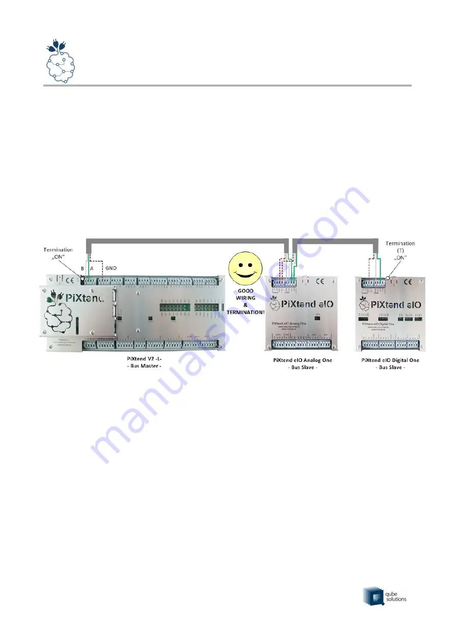
The recommended structure of the RS485 network with PiXtend eIO (slaves) and PiXtend
V2 -L- (master) is shown in the following figure:
At the beginning and at the end of the bus structure, a terminating resistor is activated.
This bus structure is no longer so widespread today. Usually, networks are built as a star
(example: Ethernet with RJ45 connectors & switches / hubs). A star could also be
produced with RS485, but this should be avoided! These and other typical wiring errors
are shown in Figure 4.
1
or 3-wire, if GND is carried along - as it is prescribed for Modbus, for example
www.pixtend.com
Copyright by Qube Solutions GmbH
19 / 119
Figure 3: Bus topology – RS485


