background image

Scalar i2000 Installation Guide

243

13

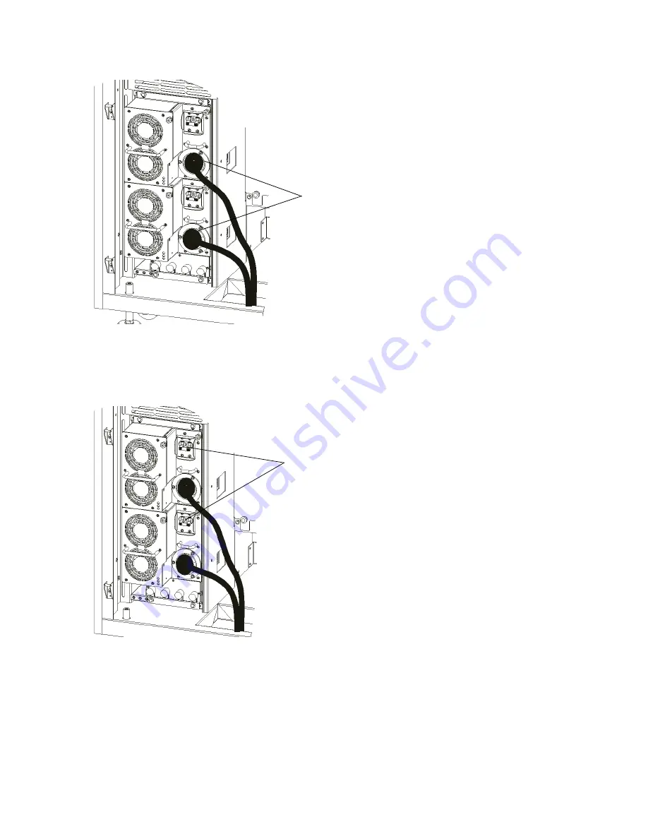
Insert the power cords into the power distribution units and turn them clockwise.

14

Plug the two power cords into the power source.

15

On both power distribution units, toggle the power switch to the up (I) position to turn on the power. If 
you have power coming to other modules of the library, they must be turned on as well.

16

Detach the ESD strap and close the door.

17

To turn on power to the library, press the 

Power

 button on the indicator panel.

The library begins to boot up. Within five minutes, the LMD display appears on the library’s touch 
screen. A library with only a few drives usually will be fully powered on and ready for use within 10 
minutes. However, if a library is large with a high number of drives, it can take more than an hour for the 
library to fully power on, complete its discovery process, and become ready for use. During the power-
on process, the 

Robotics Enabled

 indicator flashes. When the library is fully up and ready to receive 

commands, the 

Robotics Enabled

 indicator turns solid green.

plug the power cables into
the power distribution units

turn both power switches
to the on position (I)

Содержание Scalar i6000

Страница 1: ...6 66881 01 A Scalar i6000 Installation Guide Installation Guide Installation Guide Installation Guide...

Страница 2: ...t 2010 by Quantum Corporation All rights reserved Your right to copy this manual is limited by copyright law Making copies or adaptations without prior written authorization of Quantum Corporation is...

Страница 3: ...ronic Equipment 5 Product Model Number 6 Explanation of Symbols and Notes 6 Other Documents you Might Need 6 Getting More Information or Help 7 2 Getting Started 9 Unpacking and Inspecting 9 Checking...

Страница 4: ...ning the Upper and Lower X Axis Rails 41 Attaching the Middle X Axis Rail 43 Aligning the Middle X Axis Channel 45 Aligning the Middle X Axis Rail 46 Verifying the Middle X Axis Rail Alignment 47 Veri...

Страница 5: ...Drives 112 Pre LTO 5 SNW Drives 112 LTO 5 SNW Drives 112 Cabling Configuration for Native Attach Drives 112 Pre LTO 5 Native Attach Drives 112 LTO 5 Native Attach Drives 113 Interaction of Physical Ca...

Страница 6: ...and Time 169 Setting up E mail 170 Setting up Notification 171 Enabling Logical Serial Number Addressing for Drives 175 Using LDAP 176 LDAP Server Guidelines 176 User and Group Access 176 OpenLDAP 2...

Страница 7: ...es to the I O Management Unit 257 Installing the I O Management Unit Cooling Assembly 257 Installing a Control Management Blade 259 Installing an FC I O Blade 260 Installing an Ethernet Expansion Blad...

Страница 8: ...preting LED Codes 351 Interpreting Blade Status LEDs 351 Actions Based on LED States 353 Interpreting Drive Status LEDs 354 Interpreting Fibre Port Link LEDs 356 Drive Sled Fibre Channel Link LED 356...

Страница 9: ...Table 11 Test Results 313 Table 12 Automatic E mail Notification 333 Table 13 Customer License Verification 334 Table 14 Library Partitioning 334 Table 15 FC I O Blade Default Port Settings 335 Table...

Страница 10: ...States 359 Table 26 Explanations of MCB Ethernet Port LED States 360 Table 27 Explanations of LBX Terminator LED States Version 01 362 Table 28 Explanations of LBX Terminator LED States Version 03 36...

Страница 11: ...re 11 LTO drive examples 106 Figure 12 Example of Drives Connected to FC I O Blades 115 Figure 13 Example of LTO 5 Drives Connected to Ethernet Expansion Blades 120 Figure 14 Example of Direct Attache...

Страница 12: ...2 347 Figure 38 LBX Connections LBX2 Gen 3 348 Figure 39 Comparison of LBX Terminator Versions 349 Figure 40 LBX Board and Terminator Installed 349 Figure 41 Locations and Colors of Blade Status LEDs...

Страница 13: ...Be aware that improper use may result in bodily injury damage to the equipment or interference with other equipment Note Be sure to read all operating instructions in this manual and in the System Saf...

Страница 14: ...from the normal working area You can access the internal components of the library through the access and service doors only When the library is powered on the interlock on the access door is active...

Страница 15: ...ponents and equipment clean during work Maintaining a clean working environment promotes safety Clothing must be in compliance with the following safety guidelines Clothing must not have metal fastene...

Страница 16: ...COMES INTO CONTACT WITH A LIVE PART OFTEN CANNOT BREAK LOOSE FROM THE PART A SECOND PERSON MUST STAND NEAR THE MAIN CIRCUIT BREAKER READY TO IMMEDIATELY SWITCH IT OFF IF A HAZARDOUS SITUATION OCCURS...

Страница 17: ...electronic equipment The separate collection and recycling of your waste equipment at the time of disposal will help to conserve natural resources and ensure that it is recycled in a manner that prote...

Страница 18: ...alar i6000 Unpacking Instructions 6 66934 01 Scalar i2000 i6000 Maintenance Guide 6 66880 01 System Safety and Regulatory Information Guide 6 00618 11 WARNING INDICATES A POTENTIALLY HAZARDOUS SITUATI...

Страница 19: ...information including answers to frequently asked questions FAQs You can also access software firmware and drivers through this site For further assistance or if training is desired contact Quantum F...

Страница 20: ...8 About This Guide and Your Product...

Страница 21: ...he library When you remove the packing material from the parts in the base of the module put the parts in a safe area so they will not get damaged or lost Make sure you have read the Scalar i6000 Plan...

Страница 22: ...lades 1 per 4 drives Optional 2m optical cable one per drive connects drive to FC I O blade 30m multi mode optical cables LC LC two per FC I O blade connects FC I O blade to SAN One library power cord...

Страница 23: ...provides instructions for installing the control module Each configuration must contain one control module Preparing to Install a New Multi Module Library on page 28 and Adding an Expansion Module to...

Страница 24: ...he library Installing Cartridges on page 131 gives the instructions for installing the cartridges in the two supported methods install Completing the Installation Verification Checklist on page 332 pr...

Страница 25: ...m 16 mm 13 mm 8 mm 7 mm Hex wrenches 6 mm 4 mm 3 mm 2 5 mm 2 mm Screw drivers 1 Phillips 2 Phillips Flat head Pliers and wire cutters Needle nose pliers Standard pliers Wire cutters Nut drivers 8 mm 7...

Страница 26: ...An illustration of an 8 module configuration along with figures of the front and back of both the control module and expansion modules are shown on the following pages Figure 1 Front View of an 8 Modu...

Страница 27: ...6000 Installation Guide 15 Figure 2 Front View of a Two Module Library expansion module control module access door service door I E station top cable entry touch screen indicator panel fire suppressan...

Страница 28: ...16 Getting Started Figure 3 Control Module Front View Component Location fire suppressant access magazine access door I E station picker drive sled leveling foot...

Страница 29: ...llation Guide 17 Figure 4 Control Module Rear View Component Location top cable entry power supplies drive clusters bottom cable entry power distribution units library management module I O management...

Страница 30: ...sion modules in positions 9 12 are LTO storage only modules Figure 5 Expansion Module Back View Component Location the I O management unit is installed and blades are power chassis are the library man...

Страница 31: ...ti Module Library on page 27 To install a stand alone control module complete the following procedures Positioning the Stand Alone Control Module on page 20 Lowering the Leveling Legs on page 20 Raisi...

Страница 32: ...tended location 4 Verify that the control module is positioned correctly 5 Ensure that the leveling legs are not resting on tiles that will need to be raised to accommodate cables after the control mo...

Страница 33: ...e whole control module off of the casters seven 7 half turns 3 Check each corner leg to ensure that there is pressure on the foot and you cannot turn it by hand If you have correctly given each corner...

Страница 34: ...that the level is on a clean flat and horizontal surface This surface does not have to be exactly level Wait 10 seconds for the level to completely settle and take note of the angle on the display 2...

Страница 35: ...limit the level is within compliance and is ready to be used Verifying Level Condition Required tools digital level 1 Verify the module is level front to back and left to right by placing the digital...

Страница 36: ...5 Wait at least 10 seconds for the digital level to settle between adjustments 2 Place the level on the left side inside the access door Use the following rules when leveling from front to back Rule...

Страница 37: ...fy that all four leveling legs are carrying load and that the control module does not rock 2 Use the 24 mm open end wrench to raise the four leveling leg lock nuts to the top and tighten them against...

Страница 38: ...26 Installing a Stand Alone Control Module...

Страница 39: ...ring to Install a New Multi Module Library on page 28 If you are adding an expansion module to an existing system unit see Installing Expansion Modules after Installing the System Unit on page 37 If y...

Страница 40: ...e system unit Aligning and Bolting the Frames 1 Using the corner edges of the frames as a rough alignment position the frames together so the attachment bolt holes are aligned Verify that the attachme...

Страница 41: ...3 mm open end wrench 4 Once the frames are aligned and bolted properly together proceed to Positioning the System Unit on page 30 Note Do not overtighten the bolts Overtightening can damage the vertic...

Страница 42: ...nit has been installed Lowering the System Unit Leveling Legs Required tools 24 mm open end wrench 6 mm hex wrench or 16 mm open end wrench 1 On only the four outer edge corner legs of the system unit...

Страница 43: ...n page 37 The goal is to have the system unit weight evenly distributed across all four outer edge leveling legs when it is properly raised The system unit may or may not be level at this time Testing...

Страница 44: ...t the level in the exact spot as in Step 1 Wait 10 seconds for the level to completely settle and take note of the angle on the display 4 Rotate the level end for end so the display is facing away fro...

Страница 45: ...reading on the digital level that is 0 00 0 30 is to be considered level If the module does not meet the 0 00 0 30 leveling requirement go to Additional Leveling on page 34 If the module is sufficient...

Страница 46: ...it at least 10 seconds for the digital level to settle between adjustments 2 Place the level on the left side inside the control module access door position 2 Use the following rules when leveling fro...

Страница 47: ...Setting the Leg Lock Nuts Required tools 24 mm open end wrench 1 Verify that all leveling legs are carrying load and that the system unit does not rock 2 Use the 24 mm open end wrench to raise the lev...

Страница 48: ...Leveling Legs on page 37 Aligning the New Expansion Module with the System Unit on page 39 Inserting the Attachment Bolts on page 39 Tightening the Attachment Bolts on page 40 Setting the Leg Lock Nu...

Страница 49: ...ny of the modules 3 Verify that the expansion module is positioned correctly 4 Ensure that the leveling legs are not resting on tiles that will need to be raised to accommodate cables after the expans...

Страница 50: ...now the CM installation turn count use that count 3 Check each leg to ensure that there is pressure on the foot and you cannot turn it by hand If you have correctly given each leg seven 7 half turns y...

Страница 51: ...sides are parallel Be sure to turn the front and back legs the same number of turns 2 Verify that the attachment holes are aligned If not adjust the leveling legs of the new module until the attachmen...

Страница 52: ...after Installing the System Unit on page 37 for each additional expansion module For libraries with seven or eight modules see Installing the X Axis Chain Trough on page 63 Setting the Leg Lock Nuts...

Страница 53: ...joint is smooth c Tighten each screw on the rail beginning at the left end Do not tighten the screw that is on the next rail at the junction between the current module and the module to the right Not...

Страница 54: ...the previous rail so that the joint is smooth c Tighten each screw on the rail beginning at the left end Do not tighten the screw that is on the next rail at the junction between the current module a...

Страница 55: ...ial center X axis rail that must be installed in module eight of the existing library This rail is 7mm shorter then standard X axis rails The shorter X rail is etched with a part number and descriptio...

Страница 56: ...g a Multi Module Library When attached the middle X axis rail must appear as shown below Note The holes will appear slightly shifted on the 7mm shorter rail middle X axis X axis rail channel 1 2 3 4 5...

Страница 57: ...loose do the following a Place the centering tool over screw 3 and into the counterbore of the X axis rail b Holding the centering tool in place tighten screw 3 c Repeat for screw 8 Note You only nee...

Страница 58: ...crews that were tightened Step 1 on page 45 Aligning the Middle X Axis Rail 1 Loosen the five 8 mm nuts on the X axis rail alignment tool part number 3 00147 01 Once the nuts are loose separate the tw...

Страница 59: ...feel the junction Verifying the Middle X Axis Rail Alignment 1 Place the digital level on the lower side of the control module X axis rail between screws 3 and 4 as counted from the left Record this...

Страница 60: ...fy that the rail is still within tolerance then tighten the remaining screws d Repeat Step 4 for each expansion module The X axis rails should now be level If you need to attach and align the middle X...

Страница 61: ...the front edge of the Y drive mount so that it is aligned with the scribe mark on the lower left end of the control module s upper and lower X axis rail b Verify that the upper X axis bearing is with...

Страница 62: ...irements If the library configuration will be less than eight modules use the tensioner bracket and hard stop you removed previously Proceed to Eight Modules or Less Configuration on page 50 To add ex...

Страница 63: ...ich is provided in the installation kit The new tensioner bracket has a vertical slot instead of a hole on the bottom left 1 Confirm the tensioner assembly in the installation kit is anodized black an...

Страница 64: ...tensioner bracket 4 Use a 3 mm hex wrench to install the fours screws that attach the X axis tensioner to the substrate of the last expansion module in your library configuration 3 mm screws Replaceme...

Страница 65: ...be less than eight modules follow the Eight Modules or Less Configuration on page 53 If the library configuration will be nine modules or more follow the Nine Modules or More Configuration on page 56...

Страница 66: ...was removed as part of the disassembly procedure on an existing library See Step 5 on page 79 The clamp is connected to the X axis carriage on a new library 4 To attach the belt to the right side of t...

Страница 67: ...belt into the left side of the clamp and tighten the 2 5 mm screw to secure the belt in place 8 Secure the belt clamp to the X axis carriage by installing the two 4 mm screws through the X axis carri...

Страница 68: ...Configuration on page 53 and then complete the steps below The longer belts have an initial stretch on install You must make certain the tensioner arm is to the left of the 5mm mark and that the gap...

Страница 69: ...en reinstall the belt to the left side of the X axis belt clamp using the 2 5 mm hex wrench 7 To reinstall the x axis tensioner assembly rotate it counter clockwise and then push it upwards 8 Use a 3m...

Страница 70: ...or to the home position in the control module so you can install the X axis chain assembly Installing the X Axis Chain Assembly The X axis chain that has been removed will not be used in the new confi...

Страница 71: ...3 mm hex wrench secure the X axis chain assembly W8 to the bottom of the control module using two 3 mm screws 3 Connect the X axis chain W8 connector from the control module bulkhead X axis chain asse...

Страница 72: ...n connector W8 to the control module bulkhead using Velcro straps 5 Use a 3 mm hex wrench to attach the X axis chain assembly W8 to the Y axis drive mount assembly using two 3 mm screws Velcro straps...

Страница 73: ...nnect the Y axis motor home sensor cable to the X axis chain assembly W8 7 Connect the Y axis chain W9 to the X axis chain assembly W8 X axis chain assembly W8 X axis sensor cable Y axis chain assembl...

Страница 74: ...able by pressing down on the hold down 9 Test the Y axis assembly by moving the accessor assembly to its home position and verifying the cables do not have contact with the cables routed up the bulkhe...

Страница 75: ...e The X axis chain trough is installed only in 7 12 module configurations Skip this procedure if the configuration you are installing has six or fewer modules Note Center the trough in modules 3 4 5 a...

Страница 76: ...of the X axis cable in the middle of the third module second expansion module 4 Lay the trough flat on the X axis cable Clip the end of the trough that was removed onto the cable and attach it using...

Страница 77: ...ew on the LBX IEX cover plate and remove the plate b Use a 2 Phillips screwdriver to remove the four thumbscrews that retain the cover plate between the top and bottom drive positions Note The cables...

Страница 78: ...2 On the new expansion module loosen the thumbscrew on the LBX IEX cover plate and remove the plate 3 Locate the W1 and W2 cables on the new expansion module LBX IEX cover plate thumbscrew W2 cable W...

Страница 79: ...he LBX board in the new expansion module to the J2 connection on the LBX board in the control module or last expansion module in the existing configuration Note The LBX board has three versions and th...

Страница 80: ...y configuration and verify what style of terminator is needed There are two versions of the LBX terminator board card For more information see LBX Terminator on page 349 Once you have determined what...

Страница 81: ...n Guide 69 8 Use the cover plate thumbscrew to replace the LBX IEX cover plates on the modules 9 Use a 2 Phillips screwdriver to replace the cover plate between the drive positions LBX IEX cover plate...

Страница 82: ...Required tools 2 5 mm hex wrench 1 Remove the magazine storage on rack 1 in sections 1 5 on Column 4 in the last expansion module drive cluster top view of module rack 1 back rack 2 front column 4 se...

Страница 83: ...2 Install the L brackets Each bracket is attached to the module frame by two 2 5 mm hex screws 3 Locate the right side panel that was removed from the control module or previous expansion module 2 5 m...

Страница 84: ...72 Installing a Multi Module Library 4 Align the side cover with the screw holes in the expansion module screw holes screw holes...

Страница 85: ...zines removed in Step 1 on page 70 7 Reattach all of the service doors 8 Repeat steps Step 1 on page 70 through Step 3 on page 71 on each expansion module 9 Once the components are installed if applic...

Страница 86: ...cations see the Scalar i6000 Planning Guide Required tools 24 mm open end wrench 2 5 mm hex wrench 3 mm hex wrench 4 mm hex wrench 1 Verify the quantity and placement of new expansion modules 2 Verify...

Страница 87: ...t attach the right side panel to the control module or last expansion module Magazines must be removed in a top down order To remove the magazines a Remove any cartridges from the magazine b Starting...

Страница 88: ...hat attach the right side panel to the module Note Three screws are located at the front corner post three at the back corner post and three at the storage wall 2 5 mm screw 2 5 mm screw 2 5 mm screw...

Страница 89: ...i6000 Installation Guide 77 3 Lift the right side panel off the module and set it aside until the expansion module install procedure calls to reinstall it on the last expansion module screw holes scre...

Страница 90: ...e the three L brackets that mount the side panel to the storage wall and set them aside The L brackets will be reused to attach the side panel to the last expansion module 5 Reinstall the magazines th...

Страница 91: ...m the X axis carriage 3 Turn the X axis belt clamp assembly over 4 Use a 2 5 mm hex wrench to loosen the two screws on the belt clamp assembly 5 Take the X axis belt off the X axis belt clamp assembly...

Страница 92: ...emove the four 4 screws that are attaching the X axis tensioner bracket to the X axis channel in the control module or last expansion module 2 Use a 3 mm hex wrench to remove the X axis hard stop Note...

Страница 93: ...gh 10 2 Lift the rail from the frame and set aside Note You only need to remove the middle X axis rail from module eight if you are adding expansion modules to an existing eight module library Later y...

Страница 94: ...is home sensor cable by flipping up the hold down 2 Disconnect the Y axis chain W9 from the X axis chain assembly W8 3 Disconnect the Y axis home motor cable from the X axis chain assembly W8 hold dow...

Страница 95: ...hing the X axis chain assembly W8 to the Y axis drive mount assembly 5 Using the 3 mm hex wrench remove the two screws securing the X axis chain assembly W8 to the bottom of the control module 3 mm sc...

Страница 96: ...the X axis chain W8 to the control module bulkhead 7 Disconnect the X axis chain W8 connector from the control module bulkhead 8 Remove the X axis chain from the module and discard it appropriately I...

Страница 97: ...ctions on the LBX board 3 Determine your library configuration and verify what version of LBX terminator is needed There are two versions of the LBX terminator board card For more information see LBX...

Страница 98: ...o your wrist and to an unpainted surface inside the door 3 Unscrew the thumbscrew and remove the LBX IEX cover plate 4 Disconnect all cables from the LBX the LBX cable W1 internal Ethernet cable W2 LB...

Страница 99: ...he metallic standoffs 6 Remove the IEX and LBX boards connector J14 plug W3 to lower drive cluster connector J1 plug W1 to BPI or from previous LBX connector J4 plug W2 to BPI or from previous LBX con...

Страница 100: ...you should use care when inserting the LBX board into the space above the metallic standoffs 4 Plug the IEX board into the new LBX board Reconnect all cables to the LBX the aisle light cable the LBX c...

Страница 101: ...it with an IEX2 card Removing the IEX Board Required Tools None FRU ID 105 IEX board 1 If the library is not shut down shut down the library For more information see Shutting Down the Library on page...

Страница 102: ...Replacing the IEX Board Required Tools None FRU ID 105 1 If the library is not shut down shut down the library For more information see Shutting Down the Library on page 232 2 Attach the ESD strap to...

Страница 103: ...Plug the IEX board into the new LBX board 5 Use your thumb to snap the IEX board onto the two standoffs 6 Replace the LBX IEX cover plate and tighten the thumbscrew 7 Detach the ESD strap and close th...

Страница 104: ...92 Installing a Multi Module Library...

Страница 105: ...ansion modules that contain tape drives require two independent AC power sources The power cable length for each of these inputs is 14 feet 4 26 m See Table 2 on page 93 Table 2 Electrical Specificati...

Страница 106: ...on units in each module are needed if you want redundant power 4 On each of the power distribution units set the circuit breaker switch to the up I position Fan power supplies will start but library p...

Страница 107: ...n it can take more than 90 minutes for the library to fully power on and the Library Management Console to be displayed on the touch screen During this time Working will be displayed on the screen Dur...

Страница 108: ...ator panel Wait until the system is fully powered up and running and then continue with the instructions in Configuring the Library on page 153 Figure 6 Library Management Console Touch Screen You are...

Страница 109: ...hapter assume that you are installing drives and blades in a new library If you are installing drives in a new library the library is shipped with the frames preconfigured to accept the drive quantity...

Страница 110: ...O 1 or LTO 2 LVD SCSI IBM LTO 1 LTO 2 LTO 3 LTO 4 HP LTO 3 LTO 4 LTO 5 FC Multi mode Quantum SDLT 320 LVD SCSI Quantum SDLT 600 FC Quantum DLT S4 FC LTO drives can be connected directly to hosts to th...

Страница 111: ...not reformat LTO 1 cartridges The drives will write to the cartridges in the LTO 1 format 100 GB capacity Reads Writes Not compatible Not compatible Not compatible Not compatible Not compatible Not c...

Страница 112: ...VS1 data cartridge The SDLT 600 tape drive will eject a data cartridge written in DLT formats other than DLT VS160 All DLT cartridges are the same size which means they will use the same magazines in...

Страница 113: ...Sequence An example of the numbering sequence for all drives except SDLT 320 SCSI drives is shown in Figure 7 below For information on the library s coordinate system see Storage Addressing System Ove...

Страница 114: ...There can be a maximum of four drives connected to each FC I O blade installed in the I O management unit FC 1 and FC 2 are reserved for connections to the SAN or hosts Figure 8 Fibre Channel I O Blad...

Страница 115: ...ernet Expansion blades EEB to drives Figure 9 shows the numbering bottom to top on the Ethernet Expansion blade There can be a maximum of six drives connected to each EEB installed in the I O manageme...

Страница 116: ...O management unit Figure 10 I O Management Unit Bay Layout Note Bay 2 is reserved for the control management blade CMB Bay 1 is not used bay 1 not used bay 3 first FC I O blade bay 5 third FC I O bla...

Страница 117: ...sled positions However gaps between drive locations are not supported Drives must be installed in each module in the order shown in Figure 7 on 101 The control module must be fully populated with 12 d...

Страница 118: ...e You might need to tilt the drive up or down in order to engage the rails Once inserted the drive should be flush with no gaps above below or on either side The screws must line up with the screw hol...

Страница 119: ...er the FC or SCSI drives to a host proceed to Attaching FC and SCSI Drives Directly to Hosts on page 124 If you are connecting the FC drives to I O blades you will first follow the instructions in Ins...

Страница 120: ...ty of tape operations Each blade provides two host communication ports and four connection ports to drives Each Ethernet expansion blade supports 6 LTO 5 tape drives If there are FC I O blades or Ethe...

Страница 121: ...ess up and out to open the latchhooks on each side of the blade 7 Evenly apply pressure to both sides of the blade and slide it into the I O management unit until the latchhooks begin to move towards...

Страница 122: ...ade Push the latchhooks towards the middle You will feel the latchhooks lock into place 9 Detach the ESD strap If you are not adding any optional hardware you are now ready to power up the library App...

Страница 123: ...n each FC I O blade that can be connected directly to the host or to the SAN A partition can be LUN mapped through a direct attached LTO 5 drive This chapter contains the following sections Drive Cabl...

Страница 124: ...s the configuration should spread the Library Control Paths across several FC I O blades to minimize the single point of failure It is logical to combine drives from a particular partition and the Lib...

Страница 125: ...the correct hosts for the defined partitions The physical cabling must allow connection of desired hosts to desired library partition s and drives LTO 5 drives should never be connected to both a FC I...

Страница 126: ...verview on page 132 Table 5 Cable Connection Requirements for FC Drives FC I O Blade Positions in the I O Management Unit FC Connection on I O Blade Drive Coordinates Bay 3 FC 3 1 1 1 1 1 1 Bay 3 FC 4...

Страница 127: ...o FC I O Blades Drives can only be connected to ports FC 3 through FC 6 Host connections are made through ports FC 1 and FC 2 connection to host or SAN cable from FC 3 to drive coordinate 1 1 1 1 1 1...

Страница 128: ...bles and remove the two white plastic protective caps from each end of the cable 6 Connect the Fibre optical cable to port FC 3 on the FC I O blade that is installed in bay 3 of the I O management uni...

Страница 129: ...e Channel connection on the drive 9 Repeat Step 5 on page 116 through Step 8 on page 117 for each drive that will be installed Note The FC port and drive numbers will change according to Table 5 on pa...

Страница 130: ...ical cables and put them inside the Velcro straps that are attached to the right side of the module 11 Connect the designated host to the FC 1 or FC 2 port on the FC I O blade 12 Detach the ESD strap...

Страница 131: ...library s internal Ethernet and should not be connected to an external Ethernet source External Ethernet cables should not be connected to your LTO 5 drives Note An LTO 5 tape drive cannot be connect...

Страница 132: ...LTO 5 Drives Connected to Ethernet Expansion Blades LTO 5 Drive 1 1 1 1 1 1 1 1 1 2 1 1 1 1 1 3 1 1 1 1 1 4 1 1 1 1 1 5 1 1 1 1 1 6 1 1 1 1 1 7 1 1 1 1 1 8 1 1 1 1 1 9 1 1 1 1 1 10 1 1 1 1 1 11 1 1 1...

Страница 133: ...drives 4 Remove and discard the protective covers from the ports on the Ethernet Expansion blades 5 Carefully unwrap the EEB cables 6 Connect the EEB cable to ETH 1 on the EEB that is installed in bay...

Страница 134: ...cable into the EEB port connection on the drive 9 Repeat Step 5 on page 121 through Step 8 on page 122 for each drive that will be installed and connected to an EEB Note The EEB port and drive number...

Страница 135: ...ar i6000 Installation Guide 123 10 Gather the EEB cables and put them inside the Velcro straps that are attached to the right side of the module 11 Detach the ESD strap use Velcro straps to secure cab...

Страница 136: ...in the host registry or configuration file on a UNIX host The driver refers to the binding information when the library boots You are now ready to configure the library using the instructions in Confi...

Страница 137: ...tered when swapping drives cables or locations The partition should map to a higher priority LUN than the drives Examples of the direct attach cabling for SCSI and Fibre Channel drives are shown in Fi...

Страница 138: ...into the control module Note In the example shown in Figure 14 the SCSI drives 2 4 6 8 10 and 12 must be terminated by installing an appropriate terminator on the ports shown CAUTION Do not cable a dr...

Страница 139: ...27 Figure 15 Example of Direct Attached Library with FC Drives cables routed library controller directly from the secure the cables drives to hosts to host cable or the SAN to the sides of the modules...

Страница 140: ...optic cable to the port of the MCB in the control module 8 If e mail notification is going to be used to monitor the library connect the Ethernet cable that is provided with the library to the Ethern...

Страница 141: ...the end that connects to the tape drive with the name of the host and the end that connects to the host with the name and location of the tape drive This will help you find the correct cable if there...

Страница 142: ...all cable to the right side of the module and either up through one of the three holes in the top or down through the opening at bottom of the control module Secure the cable to the right side using...

Страница 143: ...s can be loaded two ways Import If the library will have more than one partition insert cartridges in the I E station and use the Library Management Console LMC to import the cartridges For more infor...

Страница 144: ...designations inside each module These will always be either 1 or 2 with 2 being the inside of the access door Figure 16 Aisle Module and Rack Numbering Locations Section There are 10 sections in a rac...

Страница 145: ...e installed on rack 1 of a control module or expansion module they replace the storage in columns 1 and 2 Because drives are installed from the bottom to the top you will lose the storage starting in...

Страница 146: ...sections 1 through 4 top to bottom When you have an I E station installed on rack 2 there are no cartridges in columns 3 and 4 of sections 1 5 See Figure 18 for an illustration Note In Figure 18 on 1...

Страница 147: ...in aisle 1 module 1 and rack 1 That is why the first three numbers in the comma separated list are 1 1 1 The last three numbers represent the address on the linear storage assembly Figure 19 Example L...

Страница 148: ...e you to specify cartridge locations These coordinates are reported in parenthetical format each element separated by commas In parenthetical format the location for the device listed in the Load Driv...

Страница 149: ...a or multiple partitions in the library If the library has cartridges with identical barcode labels the library will issue a ticket notifying you of the problem Areas in the LMC where media IDs are li...

Страница 150: ...For SDLT II media barcodes the library dynamically supports 1 to 6 characters for volume serial number plus a one character media type identifier The image below is an example of a supported SDLT II...

Страница 151: ...code labels to the cartridges You will use the I E station to load cartridges 1 Make sure that you are viewing the partition into which you want to import a cartridge 2 From the View menu select a par...

Страница 152: ...st of cartridges in the I E station displayed The following table describes the elements on the Import Media dialog box Element Description IE Station The number of the I E station which is the same a...

Страница 153: ...tridge located I E station The number of the I E station which is the same as the control module or expansion module that contains it All 24 slot single door I E stations are numbered starting with 1...

Страница 154: ...ot The media is not inserted in the slot upside down see Figure 22 The media is not dropped while loading it into the library Note To ensure the proper operation of tape cartridges pickers and drives...

Страница 155: ...of the control module or expansion module 5 When you have completed your bulk load make sure all cartridges are inserted completely 6 Close the access door of the control module or expansion module 7...

Страница 156: ...144 Installing Cartridges...

Страница 157: ...uchscreen is also available as a Java applet using a Web browser Launching the Remote Client In order to manage your library remotely point your client to the IP address of the library Only one admini...

Страница 158: ...ng external IP addressing If you set up the same IP subnet for both the internal and external IP networks for example 10 10 X X the library will become unusable If you change the internal IP addressin...

Страница 159: ...want to shut down the library You must shut down and restart the library CAUTION Setting the internal IP network to be on the same subnet that the external IP network is on causes library failure and...

Страница 160: ...ed Configuring Access for Network Services The Services tab on the Security Configuration dialog box enables you to entirely prevent all external access to the library or allow access according to oth...

Страница 161: ...erver can determine whether the IP address that is assigned to the MCB is still valid ICMP is enabled by default SSH To prevent Secure Shell access to the library select Disable To allow SSH to run on...

Страница 162: ...specified here Otherwise callbacks fail because the library s firewall blocks outbound packets designated for out of range ports Service Login To allow service login select Enable To prevent service...

Страница 163: ...If you want to permit less secure SNMP access select Enable SNMP v1 and v2 If you decide you do not want to use SNMP v1 and v2 clear the Enable SNMP v1 and v2 check box The library ignores all remote...

Страница 164: ...152 Setting up Your Library for Access...

Страница 165: ...nfiguration that must be done Configuration varies depending on the type of library and the features that will be used Before configuring the library you should review all Technical Bulletins and Rele...

Страница 166: ...re the library If you want to perform a minimal configuration using the Setup Wizard proceed to the instructions in Performing Basic Configuration on page 156 Note Select the Shift key to access upper...

Страница 167: ...configuration manually using Expert Mode proceed to the instructions in Performing Advanced Configuration on page 163 Note You cannot create partitions that include mixed media using the Setup Wizard...

Страница 168: ...ced Configuration on page 163 The interaction between drive types and partitions include the following If the library discovers two different domains of storage it will allow you to create two partiti...

Страница 169: ...create one or more new partitions 1 Click Setup Partitions Configure The Partitions dialog box appears 2 Select partition1 the default partition 3 Click Delete a If the partition is online you will b...

Страница 170: ...p the Network Configuration on page 165 for more information Date and time See Setting Date and Time on page 169 for more information For additional information on any of the steps see the information...

Страница 171: ...ense keys are not case sensitive and all inclusive For example J2BGL 22622 52C22 Click Next to continue 4 If you deleted the default partition you are given the choice of creating a partition automati...

Страница 172: ...the Library 5 Type the number of partitions for each drive type 6 Click Finish The Partition Setup dialog box appears 7 Select the partition 8 Click Create to create the partition The LUN Mapping dia...

Страница 173: ...he Network Configuration dialog box you can set the following configuration If Dynamic Host Configuration Protocol DHCP is enabled on your network select Enable DHCP automatically configures the libra...

Страница 174: ...you reach the end of the Setup Wizard click Finish to exit 13 To log off click Operation Log Off 14 Continue with the setup and configuration of the library Optionally set up e mail using the instruct...

Страница 175: ...ge 164 Setting Up the Network Configuration on page 165 Setting Date and Time on page 169 Setting up E mail on page 170 Setting up Notification on page 171 Creating Partitions on page 182 Configuring...

Страница 176: ...res not licensed by quantity are displayed as 1 in the Quantity column If you cannot locate the license keys shipped with the library you can obtain them by contacting Quantum Technical Assistance Cen...

Страница 177: ...age 166 If IPv6 is enabled but you want to configure an IPv4 connection click IPv4 Configuration on the Network Configuration submenu to display the IPv4 Network Configuration dialog Proceed to Settin...

Страница 178: ...etwork select Enable to have DHCP automatically configure the library network settings Enable makes the IP Address Subnet Mask and Default Gateway text boxes unavailable Select Disable to make the IP...

Страница 179: ...the IPv6 Network Configuration dialog box appears 1 Use the Static IP tab to disable or to enable and specify a static IP address Valid static IP addresses include link local site local and global uni...

Страница 180: ...ibrary 6 To display the Settings tab click Settings 7 Use the Settings tab to view the current IPv6 configuration settings 8 After you make the appropriate network configuration changes click OK 9 A p...

Страница 181: ...have the option of using one or two IP addresses Go to step 5 If the DNS Server has been configured through the LMC Setup DNS Configuration type the valid alpha numeric IP Addresses that are accessibl...

Страница 182: ...information into the Email Configuration Settings dialog box SMTP Server for example 192 16 68 2 You can use either iPv4 or iPv6 addresses Authentication select either Password or None If you select N...

Страница 183: ...the test message should be Test email from Scalar i6000 and the message text should include the library name version and serial number along with the date and time that the message was sent 6 Click O...

Страница 184: ...log box example 5 To set up a new e mail notification recipient click Create Note If you have previously saved a configuration and you enter a configuration change the system asks you to perform a Sav...

Страница 185: ...ialog box appears 6 In the Email Address text box type the e mail address that you want to receive notifications Do not enter multiple addresses into this box To associate more than one e mail address...

Страница 186: ...shed entering your specifications click OK on the System Setup Notification dialog box Proceed to Enabling Logical Serial Number Addressing for Drives on page 175 Level Meaning Type of Information Rep...

Страница 187: ...library location the logical serial number remains the same From the host s perspective the replacement drive is the same as the original one 1 Log on as the service user 2 Make sure that you are view...

Страница 188: ...Groups must be created on the LDAP server with names that correspond to the library partition names Users without administrator privileges must be assigned to these groups on the LDAP server to have a...

Страница 189: ...le the setup options to access a secure LDAP server which can be done using any port except 389 The default secure port is 636 If you enable this option you must retrieve the Trusted Root Certificate...

Страница 190: ...ame format to the location used to search for the login users You can search for a user in the context specified and all contexts below it Group Context This is a path in distinguished name format to...

Страница 191: ...on s the user has access 8 After you have entered the LDAP configurations click Test to verify the LDAP connection A connection with the LDAP server s is established and the library determines whether...

Страница 192: ...fferent physical connection points depending on the hardware configuration of your library The procedure for setting up and defining the control path for a partition depends on which physical connecti...

Страница 193: ...de Configuring FC I O Blade Ports on page 194 Configuring FC Host Port Failover on page 198 Enabling a Disabled Target Port on page 200 Configuring Datapath Conditioning on page 201 Configuring Switch...

Страница 194: ...ary s automatic mode to create partitions within limits based on licensing restrictions and available resources Because automatic mode is available only if no partitions currently exist you must first...

Страница 195: ...dialog box appears 4 In the Partitions column type the number of partitions you want to create for each media drive type The maximum number of partitions that you can specify is determined by the numb...

Страница 196: ...ned to the partition The library assigns the next available elements to the partition In expert mode you indicate specifically by location which drives storage magazines I E station magazines or if en...

Страница 197: ...not appear 4 In the Choose Partition Properties dialog box configure the following settings In the Name box describe the new partition In the Drive Domain drop down list select the appropriate drive...

Страница 198: ...ry does not allow it to be moved into or within the library If the library finds a valid media ID the library allows it to be moved from an I E station into a partition that contains magazines matchin...

Страница 199: ...Select Next to proceed 8 In the Choose Resource Allocation Mode dialog box select either Simple or Expert 9 Select Next to proceed To continue in Simple mode see Performing Simple Partition Resource...

Страница 200: ...e partition by specifying Number of drives Number of storage slots Number of I E station slots The quantity available for each type of resource element indicates resources not already assigned to exis...

Страница 201: ...Completed dialog box review the information to make certain it is correct 6 Click Finish The Partitions window appears showing the new partition 7 Optionally click Next to identify and view the detail...

Страница 202: ...the desired drive or drives Make sure that you select the appropriate module since the library can have drives in the control module and in any other expansion module 2 To assign a drive select its c...

Страница 203: ...alog box select the location of one or more I E station magazines Make sure that you select the appropriate module since the library can have I E stations in the control module and in any of the eleve...

Страница 204: ...n 14 In the Partitions dialog box click Finish Viewing Partition Details If you want to see settings and information for a partition but do not need to make changes view partition details Unlike modif...

Страница 205: ...4 LTO 5 or DLT Interface The type of interface used to connect to the host FC or SCSI Drives The number of tapes drives in the partition Storage Slots The number of storage slots in the partition I E...

Страница 206: ...sts or the SAN These ports are FC 1 and FC 2 By default ports FC 1 and FC 2 are in target mode The other four ports FC 3 FC 4 FC 5 and FC 6 are in initiator mode by default The default FC I O blade po...

Страница 207: ...onnectivity Port Configuration The Connectivity dialog box appears All components that provide FC and SCSI ports show in the dialog box if they are detected 2 Select a component to expand its list of...

Страница 208: ...t Because this setting is not configurable on the MCB the Speed area does not appear on the Fibre Channel Parameters dialog box when configuring the MCB FC port The MCB FC port speed is always 1 Gb se...

Страница 209: ...ore if you want to change a target port that is set to Point to Point to initiator mode you cannot do it until you first change the port connection type to Loop or Loop Preferred Consult your service...

Страница 210: ...de host access The active primary port is used for host communications while the passive standby port is kept idle The way that you configure the recovery settings determines how the failed port behav...

Страница 211: ...e the Configuration tab available 7 Accept the recovery setting default values unless an authorized representative advises you otherwise Note On the Configuration tab settings are unavailable if the c...

Страница 212: ...when port failure is caused by excessive errors on the port The only setting option is Require Intervention Link down error recovery mode sets the recovery scenario for all ports when port failure is...

Страница 213: ...ary target side data path monitoring is performed automatically and proactively The Datapath Conditioning dialog box enables you to set the level at which the data path is monitored between an I O bla...

Страница 214: ...tickets set the level to Device Datapath Test The following table describes the functionality for each data path monitoring level 7 In the Enter new Interval text box type the amount of time that sho...

Страница 215: ...4 if applicable Otherwise proceed to Configuring Host Access on page 204 Note The data path from I O blade to the drive must experience problems for two period intervals before a problem is detected a...

Страница 216: ...g software FC Host LUN Mapping During device discovery a particular partition or drive may map to a higher LUN space than is optimal for a particular application The FC Host feature allows you to crea...

Страница 217: ...nected to the blade that are attached to the host The partitions that have not yet been manually reassigned to a new map position appear in bold in the Device column The library treats partitions as d...

Страница 218: ...orking from the remote client you can use the select method or you can drag and drop the devices from the Internal LUN column to the appropriate LUN assignment in the LUN External LUN column Always us...

Страница 219: ...LUN External LUN column The previous default device map position of a remapped device is shown in gray type in the Internal LUN column 5 Click OK The FC Host map is automatically saved as part of the...

Страница 220: ...ars 2 Select a blade and then click Configure 3 To restrict access clear the check mark in the cell where the target port and the initiator channel meet All combinations are possible with one exceptio...

Страница 221: ...were at lower LUNs in order to optimize system performance Depending upon host operating system constraints it may be necessary to reboot or reconfigure the host as a result of device map changes resu...

Страница 222: ...column of the SCSI host map dialog box labeled Internal LUN lists all available devices The External LUN column on the left provides map space for IDs 0 15 associated with the selected SCSI Channel an...

Страница 223: ...nge even if you did not specify the changes If a control LUN is mapped it is always assigned LUN 0 Depending upon host operating system constraints it may be necessary to reboot or reconfigure the hos...

Страница 224: ...on the selected host are listed on this dialog box 4 Select a partition to configure and then click Next to continue All available blades on the selected partition are listed on this dialog box The L...

Страница 225: ...r blade on the same partition Map another partition this allows you to map another partition on the same host Map another host this allows you to map another host Continue and preview all the changes...

Страница 226: ...lar i6000 User s Guide The LUN Mapping Change Preview Report Print Preview dialog box appears This dialog box displays what types of changes were made to all devices The changes on the report include...

Страница 227: ...res you must install an SNW license See Enabling Licenses on page 164 For more information on Control Paths see Working with Library Control Paths on page 180 Configuring Control Path Use the Control...

Страница 228: ...e Library The Control Path dialog box appears 4 In the CP Drive Selection field select the drive you want to configure as the control path The primary Control Path Drive you selected is highlighted in...

Страница 229: ...drives support the SNW functionality An SNW license is required for each drive using SNW functionality 1 If you are not already working from the physical library select it from the View menu 2 Click...

Страница 230: ...ore information on Host configuration see the Scalar i6000 User s Guide 1 If you are not already working from the physical library select it from the View menu 2 Click Setup Device Access SNW Host The...

Страница 231: ...partitions are displayed 7 Select drives To select all drives in the Drive Access table click the Select All Drives check box to select individual drives select the check box for each drive When a dr...

Страница 232: ...ble have the following characteristics The partitions contain one or more SNW licensed drives The partitions have a Control Path drive configured 10 To make changes to a number of hosts follow steps 6...

Страница 233: ...Scalar i6000 Installation Guide 221 The Change Library Mode dialog box appears 3 Select Online 4 Click OK Proceed to Configuring Screen Saver Preferences on page 226...

Страница 234: ...uiring Online or Offline State Function Physical Library Partition Operations Import Operations Export Operations Drives Load Operations Drives Unload Operations Move Media Operations Inventory partit...

Страница 235: ...leaning media Barcode numbers do not require a specific prefix or suffix 2 Make sure that you are viewing the physical library From the View menu click the name of the physical library 3 On the menu b...

Страница 236: ...llowing To import only the selected piece of media click Menu and then click Import barcode number as cleaning media To import all media in the selected I E station magazine click Menu and then click...

Страница 237: ...k Close to close the Drive Cleaning Configuration dialog box Unassigning a Cleaning Magazine If a magazine is no longer needed for holding cleaning media first export all cleaning media from the magaz...

Страница 238: ...ge screen saver settings such as activation movement or images Select Off to disable the screen saver The current settings are cleared If you selected Custom go to Step 3 on page 226 Otherwise go to S...

Страница 239: ...select image files for all three functions To specify an image file click Browse Select the image file and then click Open The image file must be in GIF JPEG or PNG format and cannot be larger than 1...

Страница 240: ...roceed 7 Click Yes when you are prompted whether you want to generate a rescue image at the same time the remote image is saved You are asked because no rescue image currently exists If the save opera...

Страница 241: ...the touch screen after you are finished with your management session Click Operation Log Off You can also log off by clicking Log Off on the toolbar Clicking the Log Off command causes the Log On dial...

Страница 242: ...230 Configuring the Library...

Страница 243: ...I O Management Unit on page 247 Adding Blades to the I O Management Unit on page 257 Adding a 24 Slot I E Station to an Expansion Module on page 269 Adding a 72 slot I E Station to an Expansion Modul...

Страница 244: ...ick Operations System Shutdown The System Shutdown dialog box appears with Shutdown selected as the default 4 Click Yes to accept Shutdown as the default 5 A message appears that asks you whether you...

Страница 245: ...have been added to an existing library you may need to replace all of the LBX cards in all modules as well as the LBX terminator with new versions that support the new configuration For information on...

Страница 246: ...own in Figure 23 The control module must be fully populated with 12 drives before adding any drives in the first expansion module The first expansion module must be fully populated before adding any d...

Страница 247: ...Repeat Steps a through d for each partition associated with the drive installation procedure 9 On the operator panel press the Robotics Enabled button to return the accessor assembly to the home posit...

Страница 248: ...ove them from the top down 12 Use a 2 5 mm hex wrench to unscrew the retaining screws two screws per plate and remove the cover plates from the drive position 13 Reinstall the magazines above the new...

Страница 249: ...gers unscrew the retaining thumbscrews and remove the drive cover plates You must remove two cover plates for each drive that you are adding 19 Using the markings on the drive slot insert the drive sl...

Страница 250: ...omplete listing of the LED blinking codes 24 Use the instructions in Cabling on page 111 to connect the new drives 25 Detach the ESD strap and close the door The power is on 26 From the LMC click Tool...

Страница 251: ...Setup Partitions Configure The Partitions dialog box is displayed c Select the partition that include the affected magazines and click Modify d Select a partition and add the new drive s 29 To avoid c...

Страница 252: ...e control module or expansion module where you are adding the power supply chassis 3 Attach the ESD strap to your wrist and to an unpainted surface inside the door 4 On the power distribution unit s s...

Страница 253: ...dules will receive redundant power supplies as those shown below 10 Through the space the LBX occupied connect all the cables to the top of the power chassis The connections include four white connect...

Страница 254: ...n the LBX IEX cover plate using the thumbscrew connector J48S plug W5 to LBX connector J48AP plug W17 to I O management unit connector J48B plug W13 to upper drive cluster connector J48A plug W13 to l...

Страница 255: ...ator panel The library begins to boot up Within five minutes the LMD display appears on the library s touch screen A library with only a few drives usually will be fully powered on and ready for use w...

Страница 256: ...u are adding the power supplies 2 Attach the ESD strap to your wrist and to an unpainted surface inside the door 3 Use the Phillips screwdriver to loosen the thumbscrews that retain the cover plate ov...

Страница 257: ...2000 Installation Guide 245 5 Slide in the power supply and tighten the thumbscrew 6 Slide in the power distribution unit and tighten the thumbscrew power supply thumbscrew thumbscrew power distributi...

Страница 258: ...C power cord to the power source 10 On the power distribution unit toggle the circuit breaker switch to the On position I to turn on the power Note The power supply in the top position is represented...

Страница 259: ...ch the ESD strap to your wrist and to an unpainted surface inside the door 4 Use your finger or a Phillips screwdriver to loosen the thumbscrews on the cover plate where the I O management unit will b...

Страница 260: ...ill be reused later in this procedure 7 Open the box containing the new I O management unit 8 Feed the I O management unit s cables into the space behind where the I O management unit is installed The...

Страница 261: ...o secure the four retaining screws 11 Through the space behind the LBX board connect the W17 cable to the J48AP connection on top of the power chassis This is the connection to the power distribution...

Страница 262: ...er supply status cable W16 to J16 13 Insert and tighten the LBX IEX cover plate using the thumbscrew Note For more LBX version information see LBX Board and Terminator on page 345 connector J13 plug W...

Страница 263: ...ghten the two tall covers next to the drive clusters and the mid module cover plate 15 Install the grated covers on the side and top of the I O management unit tall top cover plate mid module cover pl...

Страница 264: ...re 16 Use the 7 mm nut driver to attach the cable bracket 17 Insert the I O management unit cooling assembly and push the handle up to lock it in place Use a 1 Phillips screwdriver tighten the screw 7...

Страница 265: ...the middle of the blades and into the lock position You will feel the blade pins connect with the I O management unit s backplane as the blade locks into place Figure 24 I O Management Unit Bay Layou...

Страница 266: ...oks towards the middle of the blades and into the lock position You will feel the blade pins connect with the I O management unit s backplane as the blade locks into place 20 Install cover plates over...

Страница 267: ...6 default to initiator mode 22 Route the cable through the cable keepers and down the right side of the module 23 Insert the Fibre optical cable into the Fibre Channel connection on the drive CAUTION...

Страница 268: ...splay appears on the library s touch screen A library with only a few drives usually will be fully powered on and ready for use within 10 minutes However if a library is large with a high number of dr...

Страница 269: ...ment unit cooling assembly contains the fans that regulate temperature for the I O management unit Required tools 1 Phillips screwdriver ESD strap 1 Open the service door of the module 2 Attach the ES...

Страница 270: ...y into the top slot of the I O management unit until fully seated 6 Push the latch handle into the up position 7 Use a 1 Phillips screwdriver to tighten the thumbscrew on the I O management unit cooli...

Страница 271: ...nd to an unpainted surface inside the door 3 Remove the cover plate from bay 2 the CMB slot 4 Remove the CMB from the protective anti static bag 5 Press up and out to open the latchhooks on each side...

Страница 272: ...ove the cover plate from bay where the FC I O blade will be installed The population order for the FC I O blades is shown below 4 Remove the FC I O blade from the protective anti static bag 5 Press up...

Страница 273: ...FC connectors on the tape drives 9 Remove and discard the necessary number of the black rubber protective covers from the ports on the FC I O blades 10 Carefully unwrap the six foot Fibre optical cab...

Страница 274: ...ments 12 Route the cable through the cable keepers and down the right side of the control module or expansion module 13 Insert the Fibre optical cable into the Fibre Channel connection on the drive po...

Страница 275: ...ve that will be installed 15 Gather the Fibre optical cables and put them inside the Velcro straps that are mounted on the right side of the module 16 Detach the ESD strap and close the door Note The...

Страница 276: ...d The population order for the Ethernet Expansion blades is shown below 4 Remove the Ethernet Expansion blade from the protective anti static bag 5 Press up and out to open the latchhooks on each side...

Страница 277: ...o the lock position 8 Remove and discard the plastic covers from the Ethernet connector on the tape drives 9 Remove and discard the protective covers from the ports on the Ethernet Expansion blades 10...

Страница 278: ...talled in bay 7 of the I O management unit See Cabling on page 111 for information about the cable connection requirements 12 Route the cable through the cable keepers and down the right side of the c...

Страница 279: ...ort connection on the drive 14 Repeat Step 10 on page 265 through Step 13 on page 267 for each drive that will be installed and connected to an EEB Note The EEB port and drive numbers will change acco...

Страница 280: ...e 15 Gather the EEB cables and put them inside the Velcro straps that are attached to the right side of the module 16 Connect the designated host to the port on the EEB 17 Detach the ESD strap use Vel...

Страница 281: ...he magazines are used in any partitions 3 If the Automatic Teach mode is being used disable it to perform this upgrade procedure 4 Remove the magazines in the access door from each partition s using t...

Страница 282: ...and 4 section 6 provides additional space when installing the I E station Note Make a note of the target magazine location when it is removed Keep this magazine within reach You will need it to perfor...

Страница 283: ...crew capture tool over the screw b Insert the 2 Phillips screwdriver through the disposable screw capture tool until seated on the screw c Remove the screw and set it aside Note Be careful when removi...

Страница 284: ...Set the screws aside 11 From the inside of the access door mount the I E station by first inserting the top of the I E station over the top rim flange of the door s I E station opening Once the top i...

Страница 285: ...h the I E station to the door using the six screws removed in Step 8 on page 271 13 Use a 2 Phillips screwdriver to mount the new expansion module skin onto the upper area of the access door next to t...

Страница 286: ...er onto the I E station door 15 Test the fit of the outer covers by opening and closing the I E station Adjust the door as necessary 16 Cut and remove the two cable ties that hold the door interlock c...

Страница 287: ...module cover plate the bottom drive cluster cover plate and the LBX IEX cover plate 19 Connect cable W6 to the I E station lock assembly and route the cable around the cable tray mid module cover plat...

Страница 288: ...the cutouts on the cable tray ramp secure cable W6 to the cable tray using the eight Velcro straps provided 21 Secure the cable to the expansion module frame and cable tray using the five cable ties p...

Страница 289: ...23 Route the I E station cable W6 from the I E station lock assembly following the door interlock cable to toward the rear of the expansion module Continue routing cable W6 through the drive cluster...

Страница 290: ...ewdriver to replace the top drive cluster cover plate the mid module cover plate the bottom drive cluster cover plate and the LBX IEX cover plate mid module cover plate bottom drive cluster cover plat...

Страница 291: ...ion on the access door If the target magazine is not in the correct position the library will fail calibration 27 Install four magazines into the I E station 28 Detach the ESD strap and close the door...

Страница 292: ...ssage appears in the Results field for example Command Completed 33 For a library that is already configured you must modify any existing partition that includes resources altered or removed by the ch...

Страница 293: ...iew menu b Click Setup Partitions Configure The Partitions dialog box is displayed c Select the partition that include the affected magazines and click Modify d Return the affected magazines to the ph...

Страница 294: ...over plate and the LBX IEX cover plate 8 Identify which version of the IEX card is currently installed in the library If the library contains an IEX2 card identified by a red sticker skip to Step 12 o...

Страница 295: ...allation Guide 283 9 Use your thumb to unsnap the IEX1 board from the two standoffs 10 Unplug the IEX board from the LBX board and then remove the IEX board standoffs IEX1 board connection between IEX...

Страница 296: ...resent proceed to Step 16 on page 286 Otherwise proceed to Step 14 on page 284 14 Connect the I E cable W6 to the J7 connector on the LBX board Note To complete this upgrade procedure you must replace...

Страница 297: ...W6 cable from the LBX board following the door interlock cable to the front of the expansion module allowing the W6 cable to hang near where the I E station lock assembly will be located W6 I E stati...

Страница 298: ...ewdriver to replace the top drive cluster cover plate the mid module cover plate the bottom drive cluster cover plate and the LBX IEX cover plate mid module cover plate bottom drive cluster cover plat...

Страница 299: ...ately to the right of the expansion module you are upgrading open its access door for clearance 18 To avoid scratching the new access door on the door latches of the expansion module to the right use...

Страница 300: ...m the I E lock and release the cable from the Velcro straps securing it to the cable carrier 21 Use the supplied hex wrench to remove the two screws that secure the flex cable bracket to the top of th...

Страница 301: ...6 Properly discard the old access door 27 Carefully lift the new access door from the crate and position it in front of the expansion module at a 45 degree angle 28 Lift and mount the door onto the hi...

Страница 302: ...le not the sheath and secure it to the upper damper bracket mounting hole 38 Place the second P clamp around the I E cable and secure it to the carrier bracket in the roof of the expansion module usin...

Страница 303: ...lange mounting holes with those on the access door 44 After testing the cable clearance open the access door 45 To initiate securing the I E station to the door frame before mounting it to the door us...

Страница 304: ...292 Adding Optional Hardware eight 2 5 mm screws...

Страница 305: ...screws to ensure the bottom edge of the shroud is flat against the cross bar of the door opening Make certain there is no gap 47 Repeat Step 40 through Step 45 to install the second I E station Make c...

Страница 306: ...pin connector end of the cable to the door lock connector and the 10 pin connector end to the IEM1 card 50 On the I E station closest to the door hinge tuck the cable behind the door gasket flange 51...

Страница 307: ...tions 53 Using a 3 mm hex wrench to reinstall the access door latches of the expansion module to the right of the new access door Make certain the latches are positioned correctly storage I E station...

Страница 308: ...nd create new ones See the Scalar i6000 User s Guide for more information about working with partitions 62 Assign the new I E station and storage slot in the new access to their appropriate partitions...

Страница 309: ...hardware features To qualify for the aisle light option your Control Module serial number in your i2000 i6000 library configuration must be at least 203102253 or begin with 2631xxxxx Any i2000 i6000...

Страница 310: ...nal Hardware 3 Attach the ESD strap to your wrist and to an unpainted surface inside the door 4 Start the nuts onto the threads but do not tighten them down aisle light assembly location front of libr...

Страница 311: ...uide 299 5 Slide the aisle light assembly through the keyholes and push toward the front of the library 6 Using a 7mm nut driver tighten the 4 nuts snug against the keyholes 4 nuts aisle light assembl...

Страница 312: ...he nut 10 Pull any excess aisle light cable through the P clamp towards the front of library 11 Completely tighten the P clamp nut 12 Run the aisle light cable along top panel of the frame routing it...

Страница 313: ...Guide 301 13 Remove any cable ties along this route 14 Install the three zip ties to secure the aisle light cable and any other cables routed with it in place along the frame 15 Open the service door...

Страница 314: ...cluster cover plate the mid module cover plate the bottom drive cluster cover plate and the LBX IEX cover plate 17 Complete routing the cable through the back side of the library mid module cover plat...

Страница 315: ...tion Guide 303 18 Plug the cable s 1 x 2 connector end into the LBX board connector J19 For more information on the LBX board see LBX Board on page 345 aisle light cabling aisle light cable to LBX boa...

Страница 316: ...After the Robotics Enabled Indicator turns solid green log in to the library 23 Make sure that you are viewing the physical library From the View menu select the name of the physical library 24 From t...

Страница 317: ...Click OK See the Scalar i6000 User s Guide for more information concerning aisle lights 28 Visually verify all the aisle lights in your system are on You can view the aisle lights either through the...

Страница 318: ...306 Adding Optional Hardware...

Страница 319: ...Verification Checklist on page 332 Verifying the Hardware Installation To verify the hardware follow these steps 1 Verify that the library is leveled based on the instructions in Installing a Stand A...

Страница 320: ...e the teach is completed a message appears in the Results field for example Command Completed 9 Select Configure and click Start During the calibration teach process the picker moves to the home posit...

Страница 321: ...ly must be ready and functional and the library must be powered on In addition the library must be in an offline state and at least one scratch tape must be inserted in the I E station The smaller lib...

Страница 322: ...ry alignment test performs the following tasks Performs accessor X axis and Y axis travel test also calls the FRU accessor assembly test Calibrates library and checks calibration offsets by comparing...

Страница 323: ...sure the scanner is reading properly I E Station Assembly Test The I E station assembly test performs the following tasks Locks and unlocks I E station Calibrates each I E station and check offsets co...

Страница 324: ...ller serial numbers Drive sled controller boot and application firmware versions Drive brick serial numbers and firmware versions Drive logical serial number if the library is configured for logical s...

Страница 325: ...e to an interruption or a portion of the test was run for example no scratch tape was used so must only use existing tapes An incomplete will occur when the door is opened an abort command is issued o...

Страница 326: ...rts The following sections show an example of each type of graphical report and actions to take to correct a marginal or failed result To view the graphical reports for a test click Reports on the Ver...

Страница 327: ...gnment realign the middle X axis rail and check the alignment of the top and bottom X axis rails at the location of the failure If all the joints passed testing but accessor movement failed manually m...

Страница 328: ...ive side or door side make sure that all tape magazines are installed properly on that side and that the calibration targets are correctly snapped on to the magazines If the graphical report shows a f...

Страница 329: ...hat all tape magazines are installed properly on that side and that the calibration targets are correctly snapped on to the magazines If the graphical report shows a failed result for the I E station...

Страница 330: ...sure the magazines at the location of the failure are installed properly and that the calibration targets are correctly snapped on to the magazines Make certain the magazines are fully seated in the...

Страница 331: ...ows a failed result for one or more tape magazines make sure the magazines at the location of the failure are installed properly and that the calibration targets are correctly snapped on to the magazi...

Страница 332: ...magazines make sure the magazines at the location of the failure are installed properly If there are multiple marginal results in an area review the area to make sure it is not prone to problems Also...

Страница 333: ...ly known magazines are tested If the graphical report shows a failed result for one or more tape magazines replace the affected magazines If there are multiple marginal or failed results run the libra...

Страница 334: ...re marginal or failed results inspect the picker It should rotate easily by hand and the fingers should spring into a clamped position Make sure both rotation axis belts are free of debris Also make s...

Страница 335: ...e If you choose to save directly to your hard drive the report listing and test log are combined into one text file Figure 35 shows an example of a test log It provides the following information The t...

Страница 336: ...324 Installation Testing and Verification Figure 35 Example Test Log Output...

Страница 337: ...e Verification Test is Running is displayed in the Activity area of the main LMC display 1 Log on as an admin or service user 2 Make sure that you are viewing the physical library From the View menu c...

Страница 338: ...xt to the questions You cannot continue with the installation verification test until you have completed and verified the question requests on this questionnaire Note Make sure you physically verify e...

Страница 339: ...must have barcode labels with valid volume serial volser numbers on them Also you might find it useful to write down the volser number so that you can identify your scratch tapes This procedure will n...

Страница 340: ...rification 10 Select a scratch cartridge of each media type listed on the following dialog box Note You can select one scratch cartridge per media type Each test that requires a scratch cartridge will...

Страница 341: ...lect the cartridges click Finish As the tests run the library will generate RAS tickets if problems are discovered You must close the Verification Tests dialog box to view those tickets Return to the...

Страница 342: ...raphical tab displayed Use the Graphical tab to view graphical reports and to quickly identify areas where marginal or failed results occurred Use the toolbar to navigate between graphical reports or...

Страница 343: ...ext file click Send and then specify the output location For information about how to interpret and save test logs see Verification Test Logs on page 323 14 To see the results for a previous test clic...

Страница 344: ...Failed Degraded or Warning status If there are open the RAS ticket and resolve according to the repair instructions Verify all physical components connections and cabling Visually inspect connections...

Страница 345: ...are provided for convenience there is no requirement for or limitation to 4 entries 3 Send an e mail to an address specified by the customer system administrator to confirm end to end e mail functiona...

Страница 346: ...ify that the information displayed for each Library Partitioning are correct Make sure the partition s status field states Online Table 13 Customer License Verification License Key Feature Name Status...

Страница 347: ...Access FC Host and then click LUN Mapping to verify the values Verify proper switch zoning if one or more are connected to the library Verify the host bus adapter HBA configuration and port settings...

Страница 348: ...vice door FRU ID 402 The key that opens the access door should be given to the system administrator to load the storage racks with cartridges The key that opens the service door should be given to the...

Страница 349: ...ing used in an environment that varies 9 F from the environment in which it was last calibrated If the digital level fails the accuracy test you must recalibrate the level before use Follow this proce...

Страница 350: ...level to completely settle and take note of the angle on the display 4 Rotate the level end for end so the display is facing away from you The screw on the back of the level should be on the right sid...

Страница 351: ...tical surface within 10 degrees of plumb to perform the calibration You must use the same surface s throughout the entire calibration process If at any time the calibration process fails or will not c...

Страница 352: ...the level so that it faces away from you and the screw on the back of the level is on the left side Ensure that the level is positioned in the same spot as Step 3 Wait 10 seconds for the level to comp...

Страница 353: ...utton until an upside down 4 appears on the display At this time all of the horizontal calibration settings are done 7 Stand the level on its end so the display is facing you and the text on the face...

Страница 354: ...he level to completely settle Without moving the level gently press the HOLD button until a 6 appears on the display 9 Rotate the level end for end so the display is facing you and the text on the fac...

Страница 355: ...ioned in the same spot as Step 7 Wait 10 seconds for the level to completely settle Without moving the level gently press the HOLD button until an 8 appears on the display If this last step is perform...

Страница 356: ...344 Testing and Calibrating the Digital Level...

Страница 357: ...onfigurations of nine to twelve modules Modules one through seven must contain LBX2 Gen 2 Modules eight through twelve must contain LBX2 Gen 3 If you are adding one or more expansion modules to an exi...

Страница 358: ...or Figure 36 Comparison of LBX Board Versions note connector position blue label on both connectors connector rotated 90 LBX2 Gen 01 LBX2 Gen 2 LBX2 Gen 3 J19 rotated and moved beside connector J9 red...

Страница 359: ...J15 plug W3 to upper drive cluster connector J11 connector J7 plug W6 to I E station plug W15 to door interlock connector J10 plug W11 to I O management unit connector J16 plug W16 to I O management...

Страница 360: ...ector J15 plug W3 to upper drive cluster connector J11 connector J7 plug W6 to I E station plug W15 to door interlock connector J10 plug W11 to I O management unit connector J16 plug W16 to I O manage...

Страница 361: ...Installed Note Any LBX board version LBX2 Gen 1 located in the last module in the library must be terminated using LBX terminator version 01 shown in Figure 39 Any LBX board version LBX2 Gen 2 locate...

Страница 362: ...350 LBX Board and Terminator...

Страница 363: ...atus LEDs on page 351 Interpreting Drive Status LEDs on page 354 Interpreting Fibre Port Link LEDs on page 356 Ethernet Expansion Blade LEDs on page 359 Interpreting MCB Port LEDs on page 360 Interpre...

Страница 364: ...mean see Table 16 For a description of how the blade status LEDs appear under normal conditions see Table 17 Table 16 Explanations of Blade Status LED States LED Color Represents Possible States and E...

Страница 365: ...id on also can mean that the blade s power and control subsystem firmware is autoleveling In conjunction with the blue amber LED blinking one time every 10 seconds this is a normal condition Autolevel...

Страница 366: ...y Figure 42 shows the locations of the status LEDs and the Fibre Channel link LED on the rear of a UDS 2 drive sled Figure 42 Rear View of Fibre Channel Drive Sled UDS 2 Note The blinking codes descri...

Страница 367: ...UDS 2 and UDS 3 LED Color Represents Possible States and Explanations Green Processor status Solid on solid off tape drive s main processor is not operating Blinks one time every second 1 Hz drive sl...

Страница 368: ...ds flash drive brick is powered on operating normally Table 19 Explanations of Drive Sled Status LED States Under Normal Conditions LED Color State and Explanation Green Blinks one time every second 1...

Страница 369: ...rive brick is varied off the blue status LED will be solid on Table 22 Explanations of Fibre Drive Sled Link LED States UDS 3 LED Color Represents State and Explanation Green LIP and activity Solid on...

Страница 370: ...LED blink rapidly to indicate that the blade is starting the Power On Self Test POST Blinks with other link LEDs in a racetrack pattern when all of the I O blade link LEDs blink consecutively in a clo...

Страница 371: ...Off Off No power 1 Hz Off Off Powered Down Ready for removal Off Off On Booting Flash 1 Hz Off Normal Flash 10 Hz Off Normal Identify Table 25 Explanations of EEB Ethernet Port LED States LED Color P...

Страница 372: ...ribes how to interpret the Ethernet port LED activity that you might see Table 26 Explanations of MCB Ethernet Port LED States LED Color Possible States and Explanations Green Solid on the link is up...

Страница 373: ...LEDs for the MCB Fibre Channel and SCSI ports are shown below Figure 47 shows the locations and colors of the LEDs Figure 47 Locations and Colors of MCB Fibre Channel and SCSI Port LEDs MCB port LEDs...

Страница 374: ...tor LEDs Version 01 Table 27 Explanations of LBX Terminator LED States Version 01 LED On Off Combinations Explanation 1 2 3 4 Off Off Off Off Robotics are disabled the access door is open or the LBX t...

Страница 375: ...trol module and one expansion module On Off Off On On Off The library has one control module and two expansion modules On Off Off On On On The library has one control module and three expansion module...

Страница 376: ...Power Supply LED States LED Color Represents Possible States and Explanations Green top LED AC OK Solid on power supply s AC input is above minimum requirements to operate Solid off power supply s AC...

Страница 377: ...ronment potentially involving many components or connections between initiators and targets that have been set since the initial configuration occurred Drive pooling Drives to be held in a pool or poo...

Страница 378: ...sible to any backup applications or hosts Allows the library to be able to manage the partition rather than the backup application managing the partition Use the LMP partition as a workspace for libra...

Страница 379: ...s Fibre Channel I O blade Universal drive sled UDS A sheet metal case that houses LTO or SDLT drives in the drive clusters WORM The Scalar i6000 library supports write once read many technology in LTO...

Страница 380: ...368 Glossary...

Страница 381: ...ge addressing example 135 cartridge addressing system example 135 location coordinates 136 overview 132 cartridges importing using the I E stations 139 loading 131 manually bulk loading 142 CMB instal...

Страница 382: ...ce requests 7 Host registration service See HRS I I E station adding to existing libraries 269 281 I O management unit numbering sequences 104 253 IEX replacing 90 illustration 8 module library 14 imp...

Страница 383: ...stallation 13 results installation verification test 313 road map initial set up procedure 11 set up procedure 11 S safety intended use 1 statements 1 symbols and notes 6 System Safety and Regulatory...

Страница 384: ...372 Index...

Отзывы: