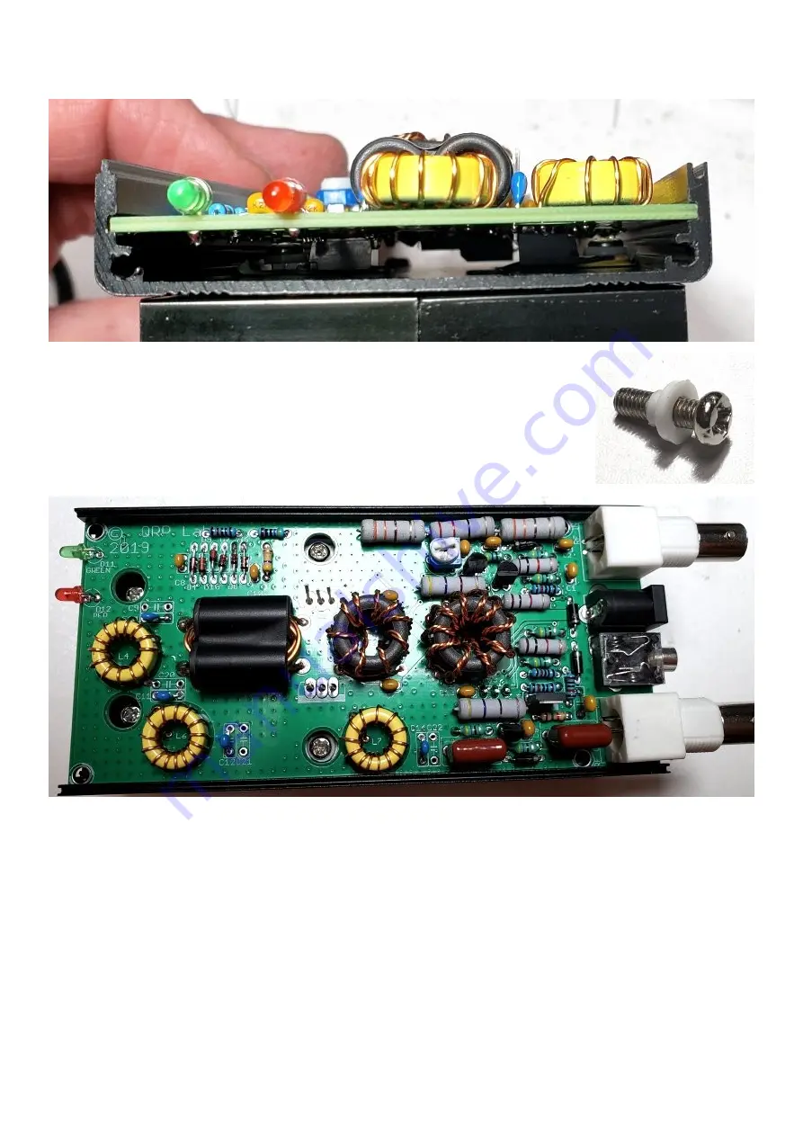
It’s worthwhile trying to shine a strong light down and eyeball that narrow gap between PCB and
enclosure, to see if it seems that everything is still in place (specifically: those silicone pads).
Now insert the final four screws.
STILL DO NOT SOLDER THE IRF510’s!
The screws at the IRF510 tabs are 9mm M3 screws with the plastic
insulating washer (see right). This is because the tab of an IRF510 is
connected to the Drain, therefore is RF-hot… not what you want shorting to
the enclosure ground or each other.
The two screws at the end of the PCB near the LEDs are 6mm M3.
Now test the insulation at the IRF510 tabs by putting one probe of a DVM in resistance (or
continuity test) mode in the head of the top screw, and the other probe on the middle pin of the top
IRF510 (Q2), which is the Drain. Be sure to touch the probe to the pin, not to the pad – remember
you have not soldered yet so the connection at the pad could be expected to be intermittent. You
should see NO CONTINUITY (infinite resistance). If you see a short-circuit it means that the
silicone insulating pad has somehow NOT done its job properly and you need to definitely open
everything up and fix that.
Repeat this test for the lower IRF510 (Q1) and its tab screw, making sure there is no continuity.
Once you are absolutely certain that there are no short-circuits, only then solder in the IRF510s. It
is recommended to solder the rightmost pin of Q2 first (ground), followed by the center pin and
then the left pin. This is because the ground pin is hardest to solder and will take the most heat; if
50W QCX PA kit assembly
1.00q
40
Содержание QCX 50W Amp
Страница 8: ...50W QCX PA kit assembly 1 00q 8...
Страница 9: ...50W QCX PA kit assembly 1 00q 9...
Страница 43: ...50W QCX PA kit assembly 1 00q 43...


