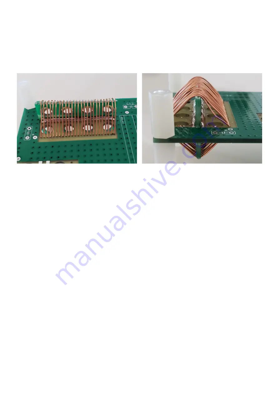
Note that the first versions of my 50W Power Amplifier development used inductors I wound using
1.6mm enameled copper wire on sawn-off 5cm (2-inch) sections of broom handle.
The first prototype PCB, I thought it would be neat, and interesting, and rather unusual and
different, to remind ourselves of how the old-timers used to wind coils. Real coils! Before toroids
became so popular. So I developed a neat PCB in which the coil was wound through holes on the
PCB. Pieces of an additional PCB design were broken off and soldered perpendicularly to the
PCB so that the coil benefited from support at 4 points in the circle.
These coils are beautiful, easy to wind, and with a highly repeatable and stable inductance.
HOWEVER, with measurements I discovered that they result in a relatively poor performance
compared to inductors wound on T50-6 toroids. The toroidal topology has inherent self-shielding
properties which prevents the field of one coil interacting with the field of another. I had spaced the
air-cored inductors as widely as I could, but PCB area is a limitation. So I suspect that the air-core
inductors, containing more wire (and hence higher resistance) may be a lower-Q than the toroidal
ones, and may also interact with each other, resulting in signal leakage. The result was slightly
lossy LPFs which resulted in several watts lower output power.
So that experiment was abandoned and the final design went ahead with T50-6 toroids.
The final PCB has two capacitors paralleled at each position. The reason with this is that it allows
me to supply sufficient capacitors to build the kit either for 40, 30 or 20m, with least waste – since
some values can be made from the combination of others. Additionally for people wishing to
experiment with other bands, it provides you the opportunity to make up the required capacitance
value but the addition of two smaller capacitors if you need to.
6.6 Transmit / Receive switching
We now come to by far the most complex part of the design, the transmit / receive switching
arrangements. Many simple low cost projects use relay switching. The problems with relay
switching are many:
•
Bulky
•
Noisy
•
Slow – too slow to allow fast switching for full break-in (QSK) operation
•
Expensive
•
Unreliable (mechanical moving parts)
•
Poor isolation at RF, can be important in some applications (unless expensive relays used)
50W QCX PA kit assembly
1.00q
53
Содержание QCX 50W Amp
Страница 8: ...50W QCX PA kit assembly 1 00q 8...
Страница 9: ...50W QCX PA kit assembly 1 00q 9...
Страница 43: ...50W QCX PA kit assembly 1 00q 43...


