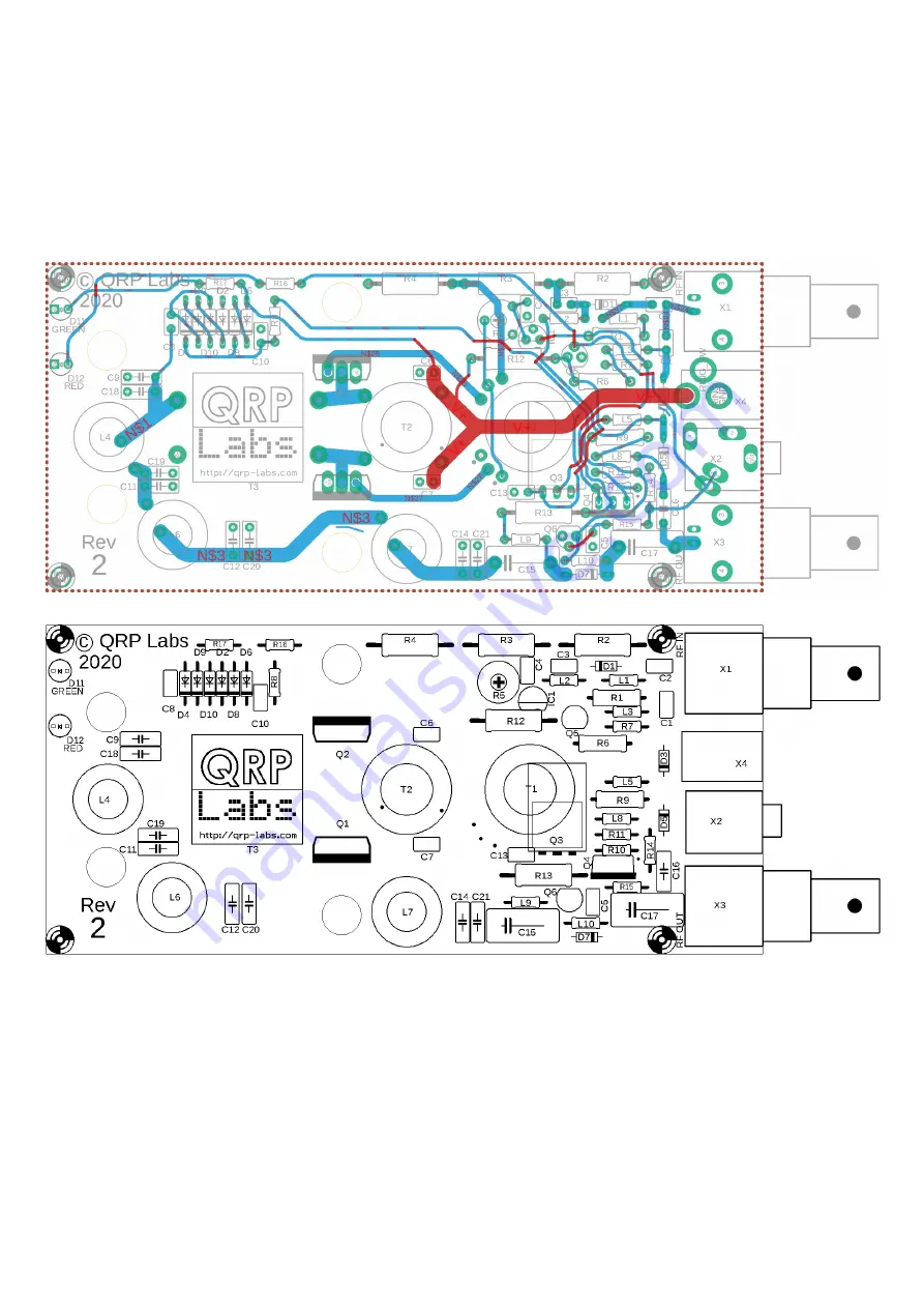
3.2 Trace diagram and parts layout
Red = Top side; Blue = bottom side; Green = pads.
There are only two layers (nothing is hidden in the middle). Not shown in these diagrams are the
extensive ground-planes, on both sides of the board. Practically everything on both layers that isn’t
a RED or BLUE track, is ground-plane! The two ground-planes are connected at frequent intervals
(not more than 0.1-inches) by vias.
3.3 Wind and install output transformer T3
We start with the installation of the transformers and inductors, which are generally the most
difficult components; doing these first means we have space around them so it is easier to access
the wires etc.
First is the output transformer, T3. The windings are made from the thick, 1mm diameter
enameled copper wire. They are wound on the two ferrite tubes, which are placed side-by-side to
make a large binocular core.
50W QCX PA kit assembly
1.00q
10
Содержание QCX 50W Amp
Страница 8: ...50W QCX PA kit assembly 1 00q 8...
Страница 9: ...50W QCX PA kit assembly 1 00q 9...
Страница 43: ...50W QCX PA kit assembly 1 00q 43...


