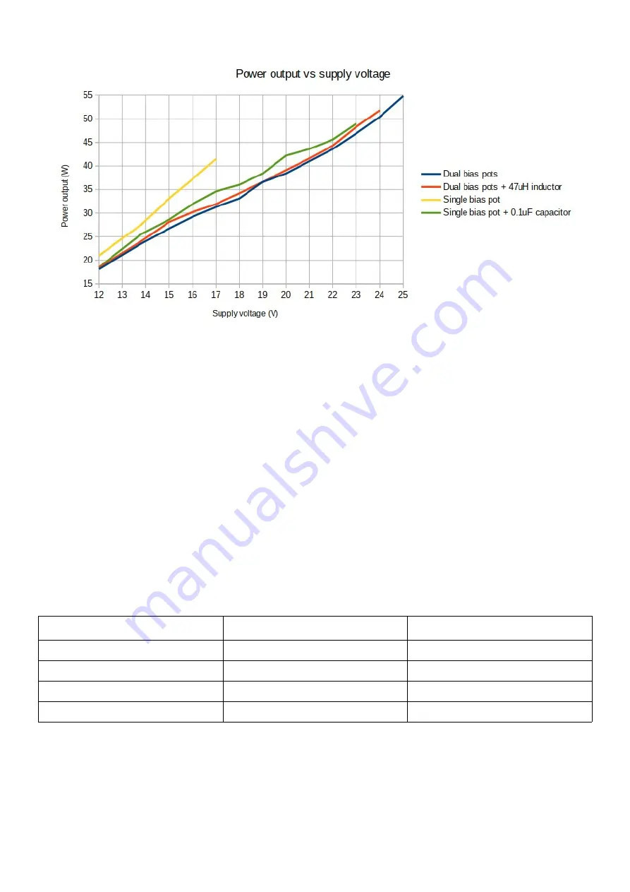
The presence or absence of the series inductor from potentiometer wiper to the transistor gates
didn’t seem to make much difference one way or the other. Some benefit was provided by using
the single trimmer potentiometer bias feeding method but there was a really significant
improvement in NOT having the 0.1uF decoupling capacitor at the trimmer wiper! It made a
significant improvement in both efficiency and in power output.
Now turning to the output transformer. This is wound on two ferrite tubes with 2:3 ratio (2 turns
primary, 3 turns secondary). They provide an easy and convenient method to get enough iron in
there at low cost. They don’t need to be glued or taped together but it helps keep things neat and
tidy.
There were two questions to answer here. Firstly, what turns ratio to use. Secondly, what material
and core topology to use.
The turns ratio determines the impedance transformation. The impedance ratio is the square of
the turns ratio. We assume a 50-ohm output (enforced by the 50-ohm dummy load used during
testing). Tested ratios were 1:2, 2:3, 1:3, 2:4. The corresponding impedances are listed in this
table:
Type
Impedance ratio
Primary impedance
1:2
4
12.5 ohms
2:3
2.25
22.2 ohms
1:3
9
5.6 ohms
2:4
4
12.5 ohms
The optimum impedance match depends on desired supply voltage and also the transistors
themselves. It is possible to increase the power output for a given supply voltage, by using a
higher impedance ratio. But the penalty of this is that the transistor must handle a correspondingly
larger current. The power supply must be able to cope with this higher current too.
With reference to the Vishay datasheet, the rated continuous drain current of the IRF510 is 5.6A
at 25C, de-rated to 4.0A at 100C. The pulsed drain current is 20A at a “pulse width limited by
50W QCX PA kit assembly
1.00q
47
Содержание QCX 50W Amp
Страница 8: ...50W QCX PA kit assembly 1 00q 8...
Страница 9: ...50W QCX PA kit assembly 1 00q 9...
Страница 43: ...50W QCX PA kit assembly 1 00q 43...


