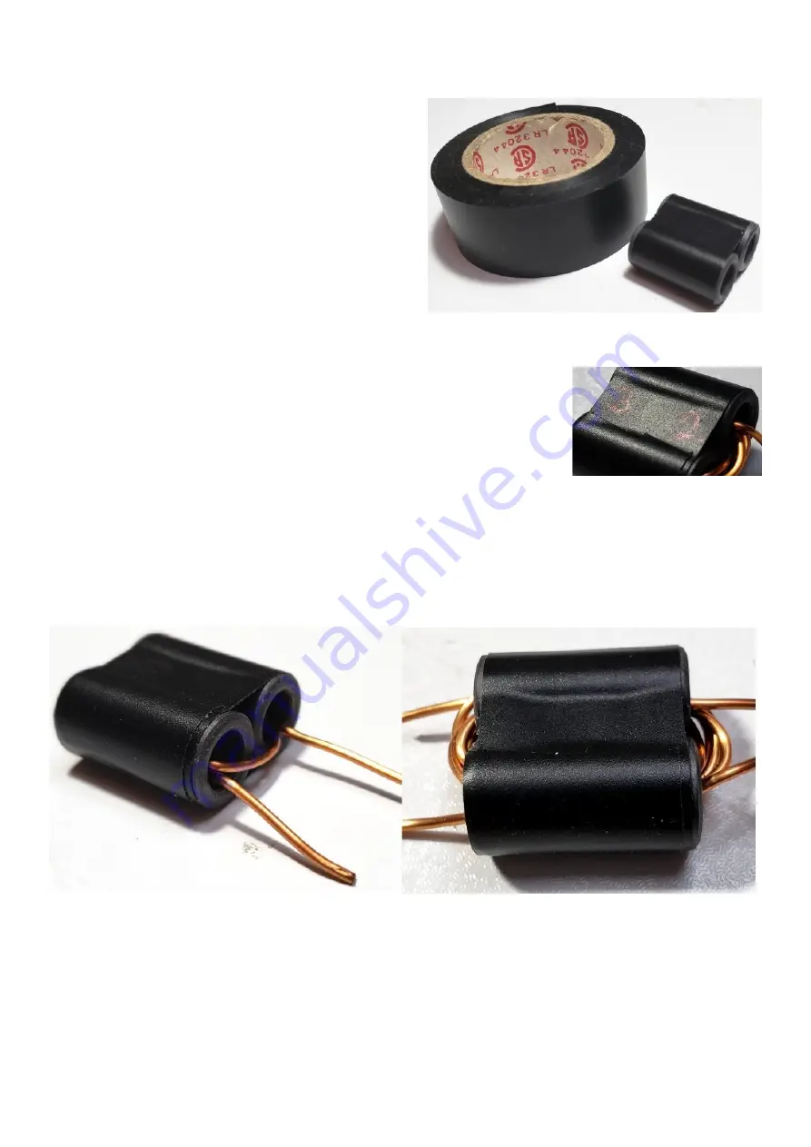
I recommend taping the two tubes together using electrical tape; it just helps keep everything
nicely held together while winding the turns. An alternative would be to epoxy glue the two tubes
together (photo, right).
The turns ratio of the transformer (and the actual
number of turns) is 2:3. Note that “1 turn” means the
wire passes through the central hole of BOTH
tubes.
It is essential to have some way of identifying the
windings. If you install the kit with the transformer in
backwards, the power output will be much lower
than expected. Unfortunately it is very easy to mix
up the transformer, and it is very difficult to tell
which is the 2-turn winding and which is the 3-turn
winding, after the windings have been completed.
For this reason it is strongly recommended to mark the two sides of the
transformer in some way. In the photo (right), this has been done this
simply with a ball-point pen. Write 3 on the left side (the secondary
winding, having 3 turns) and 2 on the right side (the primary winding,
having 2 turns). If you write on the middle part of the tape then it is less
likely that the ink will be worn off during handling of the transformer
during the installation on the PCB.
Wind the 2-turn primary first (below left). The turns start and end on the RIGHT side of the core, as
shown.
Take care not to scrape the enamel off the wire!
Wind the 3-turn secondary (below right). The turns start and end on the LEFT side of the core, as
shown.
Take care not to scrape the enamel off the wire!
The enamel on the wire is a type which burns off easily with heat from the soldering iron.
Nevertheless the wire is 1mm thick and will quickly conduct heat away; the result is that it can be
difficult to heat up the wire to a sufficient temperature that the enamel insulation burns off.
The solution to this is to gently scrape the ends of the wires, such that the enamel is removed.
Then the wire can be easily tinned with solder. Hold the wire end in a large blob of solder for about
10 seconds to ensure remaining enamel is burned away. Ensure not much solder is left on the
wire after tinning, otherwise it will be hard to fit the wire into the holes on the PCB.
50W QCX PA kit assembly
1.00q
11
Содержание QCX 50W Amp
Страница 8: ...50W QCX PA kit assembly 1 00q 8...
Страница 9: ...50W QCX PA kit assembly 1 00q 9...
Страница 43: ...50W QCX PA kit assembly 1 00q 43...


