you can easily identify any dry joints or solder bridges before they become a problem later on
when you are trying to test the project.
Triple check every component value and location BEFORE soldering the component!
It is
easy to put component leads into the wrong holes, so check, check and check again! It is difficult
to de-solder and replace components, so it is much better to get them correctly installed the first
time. In the event of a mistake, it is always best to detect and correct any errors as early as
possible (immediately after soldering the incorrect component). Again, a reminder: removing a
component and re-installing it later is often very difficult!
Please refer to the layout diagrams and PCB tracks diagrams and follow the steps carefully.
The component colour coding of the layout diagram at every step of the assembly instructions is
as follows (kind of: components past, present and future):
Components shaded grey have already been installed
Components shaded red are the ones being installed in the current assembly step
Components shaded white are the ones which have not yet been installed
VERY IMPORTANT SOLDERING ADVICE:
when soldering a component pin that goes to ground,
you need to allow extra time with the soldering iron. Ground pads are separated from the ground-
plane by what are called “thermals”, a gap between the pad and the ground-plane which is bridged
in 4 places at 0, 90, 180 and 270-degree around the circle. This is standard practice. However,
you may STILL find that it is harder to solder ground connections, because the soldering iron heat
is dissipated away more quickly. If a component ground connection is broken it can sometimes
have catastrophic consequences. So please check and recheck, particularly with ground
connections.
The following tools are required: good soldering iron, preferably 50-60W; wire-cutters; screw-
drivers; electrical insulation tape; Digital Volt Meter (DVM) or similar for continuity testing; marker
pen.
3.
ASSEMBLY
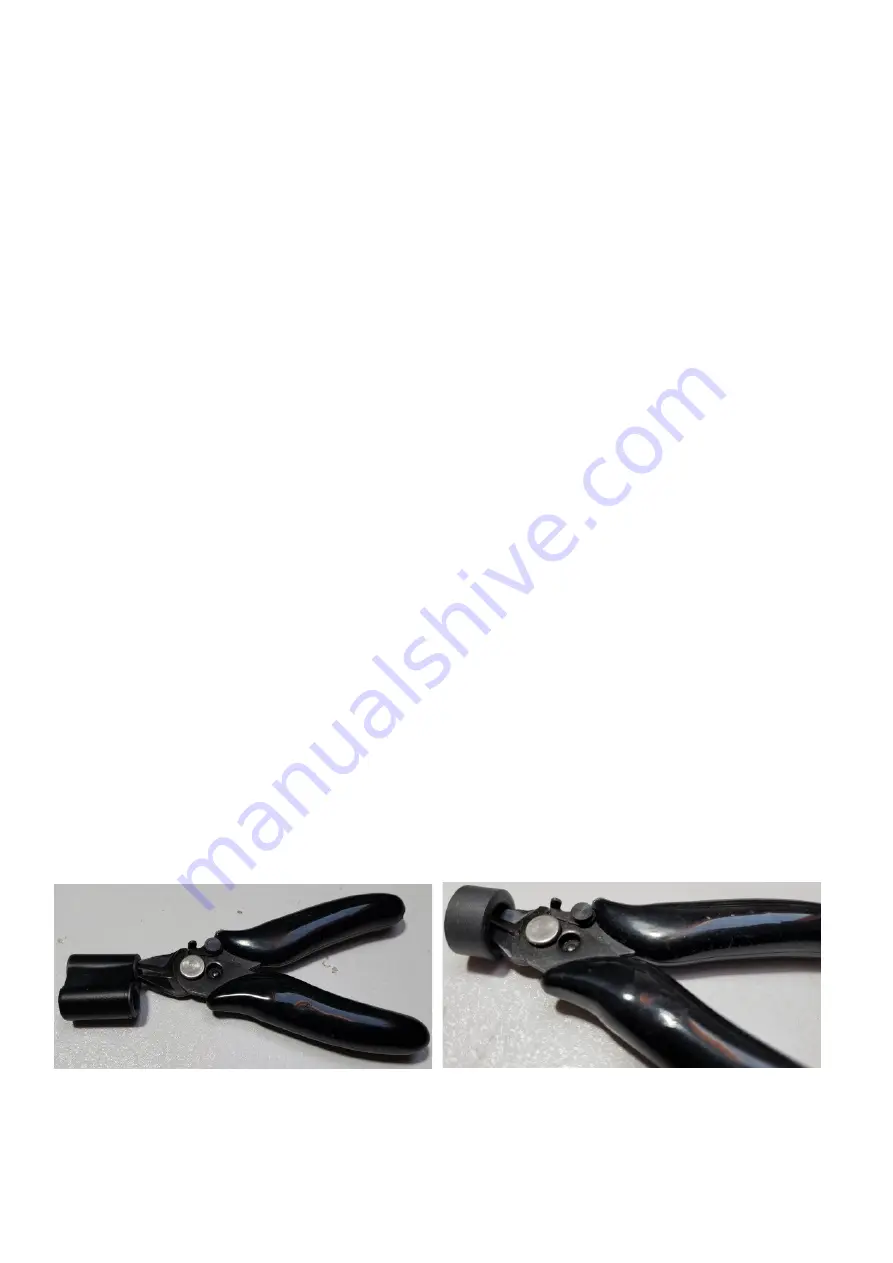
Deburr the ferrite rings and tubes by gently but firmly scraping them with a pair of wire-cutters or
similar as shown. This should smooth any sharp edges and reduce the risk of cutting the insulation
of the enameled wire.
Refer to the parts list and accompanying photographs, carefully inventory the components and
familiarize yourself with the kit contents.
50W QCX PA kit assembly
1.00q
5
Содержание QCX 50W Amp
Страница 8: ...50W QCX PA kit assembly 1 00q 8...
Страница 9: ...50W QCX PA kit assembly 1 00q 9...
Страница 43: ...50W QCX PA kit assembly 1 00q 43...


