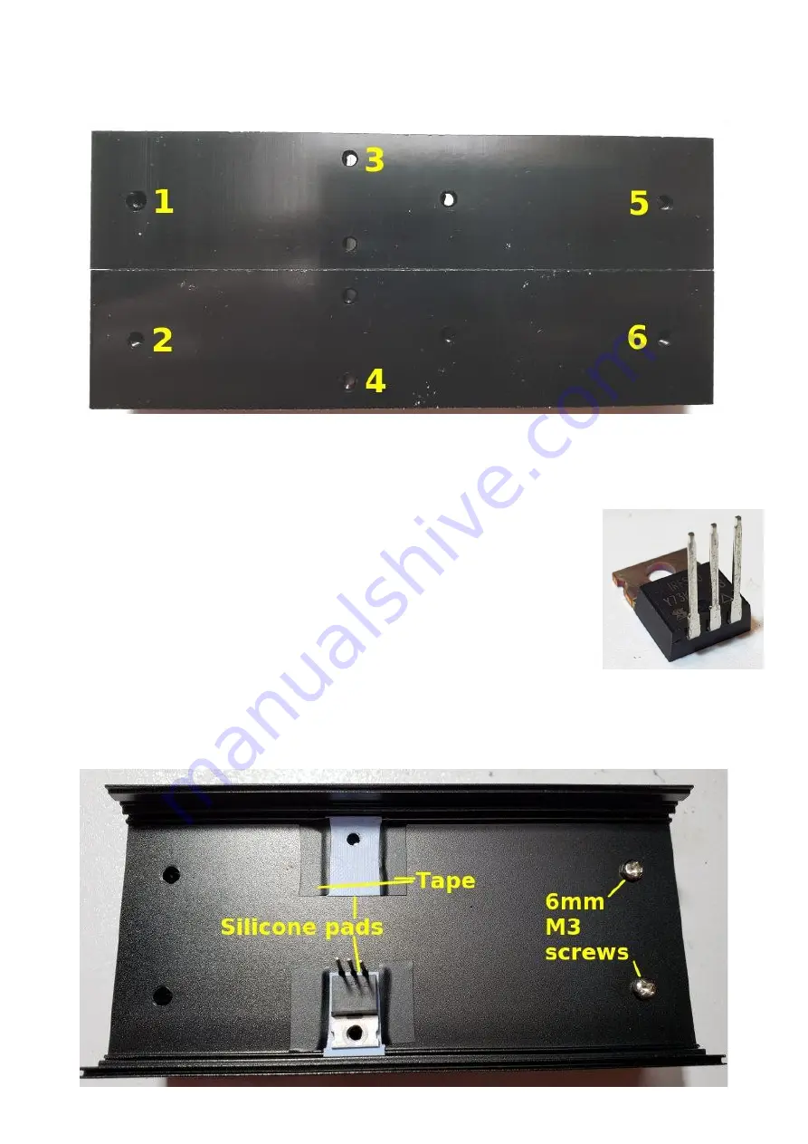
Place the heatsinks side-by-side as shown. The enclosure top will be bolted to the heatsinks with
6mm M3 screws in holes 1, 2, 5 and 6. Holes 3 and 4 will be used to bolt the IRF510’s to the
heatsink. The remaining holes of the heatsink are not used in this application.
Bolt the heatsinks to the outside surface of the top of the enclosure using two 6mm M3 screws on
the right-hand side (holes 5 & 6); these are the holes which are FURTHEST from the central holes
3 & 4. Tighten these screws but make sure that the heatsinks sit squarely on the lid of the box,
and and the heatsink holes line up with the holes in the enclosure lid.
Bend the pins upward of the IRF510 90-degrees right at the body of the
IRF510. Make sure to bend them upward not downward; you only get one
chance at this – if you bend them the wrong way then try to correct it, the
pins may well break off.
Place the light blue coloured silicone pads over holes 3 & 4. Make sure the
hole in the pad is aligned with the hole in the heatsink. The pads need to be
taped in place using small pieces of electrical tape. Otherwise they will move
during the installation. Tape only around 1mm at the edges of the silicone
pad. Do not overlap the tap and silicone pad by more than 1mm. With this small overlap, the
IRF510 will fit comfortably between and sit only on the silicone pad, as shown in the photograph
below, where an IRF510 is placed on the lower pad.
50W QCX PA kit assembly
1.00q
38
Содержание QCX 50W Amp
Страница 8: ...50W QCX PA kit assembly 1 00q 8...
Страница 9: ...50W QCX PA kit assembly 1 00q 9...
Страница 43: ...50W QCX PA kit assembly 1 00q 43...


