User Manual
PT-IPAV-E2
13
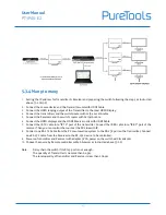
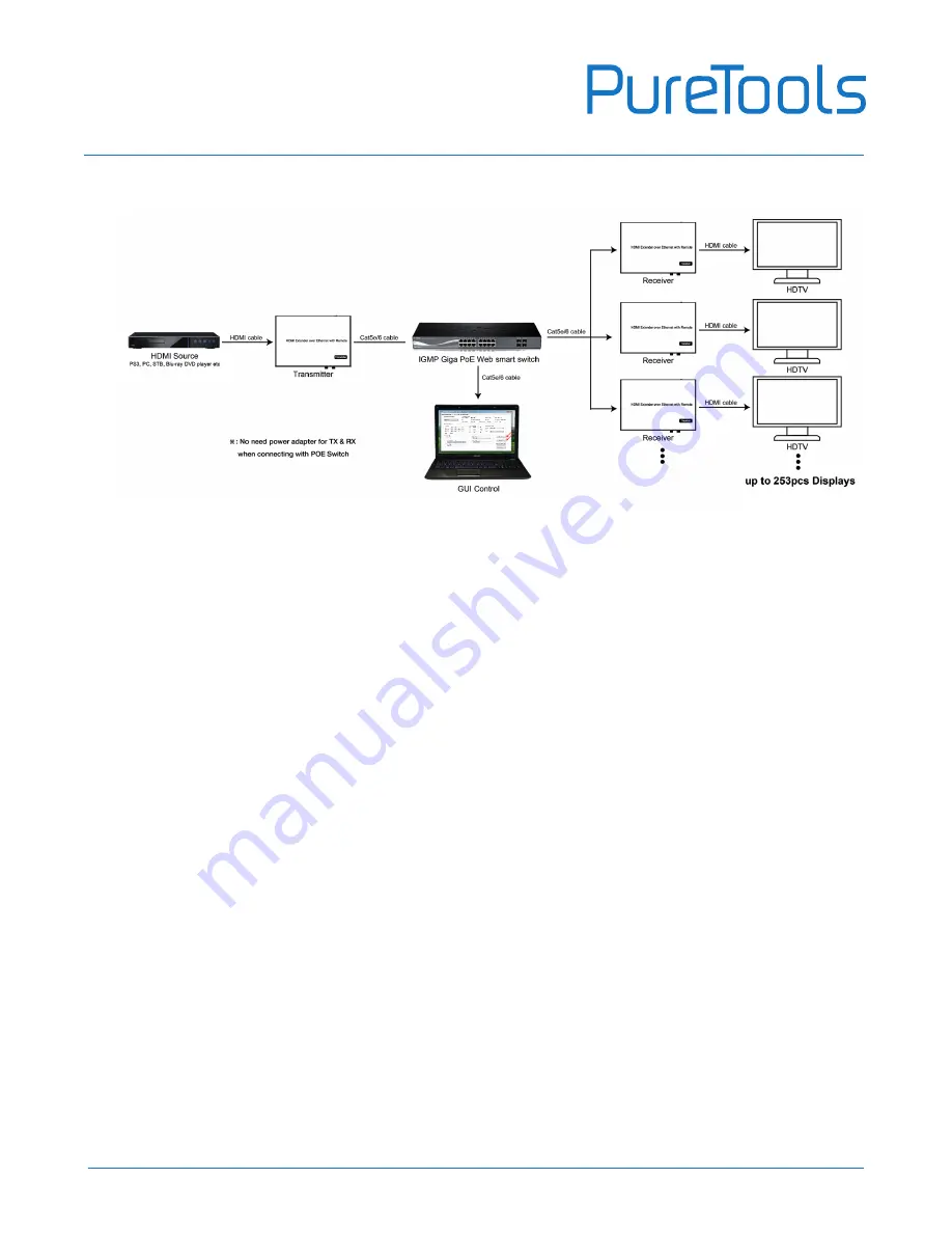
5.3.4 Many to many
1.
Setting the IP address for Transmitter & Receiver and preparing the switch following the steps as instructed
above (5.1.1&5.2)
2.
Connect the source device and the Transmitter unit with HDMI Cable.
3.
Connect the HDMI looping output of the Transmitter to the local HDMI Display.
4.
Connect the transmitters and the switch/router with cat5e or cat6 cable
5.
Connect the Receivers and the switch/ router with Cat5e/6 cable
6.
Connect the HDMI displays and the HDMI Receiver units with HDMI Cable.
7.
Connect the IR TX cable into “IR TX” port of the transmitter; Connect the IR RX cable into “IR RX” port of the
receiver. Then you can control the source at the RX side with IR.
8.
Connect one RS-232 Cable from the PC or automation system to the RS-232 port on the Transmitter; Connect
one RS-232 cable from the Receiver to the RS-232 device to be controlled.
9.
Power on Transmitter and Receiver with adapter 5V1A, power on the switch with its adapter.
10.
Choose the source by Remote controller or Web browser as instructed above (5.1.2)
Note:
Daisy chain the switch if its RJ45 port is not enough.
The quantity of Transmitter is no more than 64 pcs.
The total quantity of Transmitter and Receiver is less than 256 pcs
Содержание PT-IPAV-E2-RX
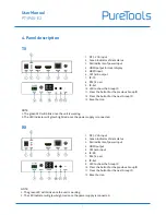
Страница 6: ...User Manual PT IPAV E2 6 How to connect the IR Cable 4 1 Panel Drawing Transmitter ...
Страница 14: ...User Manual PT IPAV E2 14 Note The total qty of TX RX Switch is less than 256pcs ...
Страница 21: ...User Manual PT IPAV E2 21 Step 6 Click Next Step 7 Choose RTP MPEC Transport Stream ...


