93-520-20 Issue 3.3
Page 14 of 60
CirrusPro Engineer’s Manual
2.3
General Cabling Requirements
All wiring associated with the system must conform to the current Wiring Regulations, and cabling
must conform to the relevant National Standards Specifications. Recommended cable separation for
electromagnetic compatibility in buildings must be followed.
Where screened cables are used it is important to ensure that screen continuity is maintained between
cable segments. Any screen wiring in the panel enclosure must be sleeved and securely bonded to
the earth.
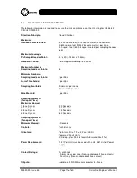
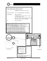
The illustration on the following page shows the location and signal level details for the Cirrus Pro.
All connections to third party equipment must be installed to the relevant manufacturers instructions.
Cirrus Pro network must be wired according to the details given in Section 2.5 below.
2.4
Insulation Testing of Cabling Prior to Connection
Before connecting any external cables, tests should be carried out using a 500V DC insulation tester
(Megger
®
). The insulation readings between each cable core, and each cable core and ground must
be greater than 10M
Ω
.
The CirrusPro or associated devices must not be connected to any cables when high
voltage insulation tests are being performed on the cabling. The cabling must be
completely discharged prior to connection. Equipment connected to the cabling during
insulation tests will be damaged by the high voltages used, invalidating any warranty.
2.5
RS485 Suggested Cabling Specifications
Cable type
Twisted-pair conductors within a cable shield and jacket
Conductor type
Stranded cores within insulation
Suggested Cable
Beldon 8723 - 2 pair screened data cable 22 AWG or equivalent
Maximum Total Length
1km
RS-485 network drivers are designed to drive one twisted pair. Network topologies such as the star or
tree are not recommended by the standard.
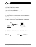
Ground the Shield/Screen.
Using the shield/screen as a third conductor for reference is the preferred method of ‘grounding’ the
network. Connect this to the ground of the Cirrus Pro. Avoid connecting the reference conductor to
more than one earth/ground point.
This helps to ensure that signals are correctly interpreted and is sometimes referred to as ‘three wire’
RS-485.
The ground of the transmitting device should thus be at the same level as the ground of the receiving
device, helping to ensure that the receiver correctly sees the data levels.
When installing RS-485 networks, especially within electrically active areas, ensure common ground
reference between network points.


