


MVI56-MCM
♦
ControlLogix Platform
Start Here
Modbus Communication Module
Page 12 of 159
ProSoft Technology, Inc.
July 24, 2008
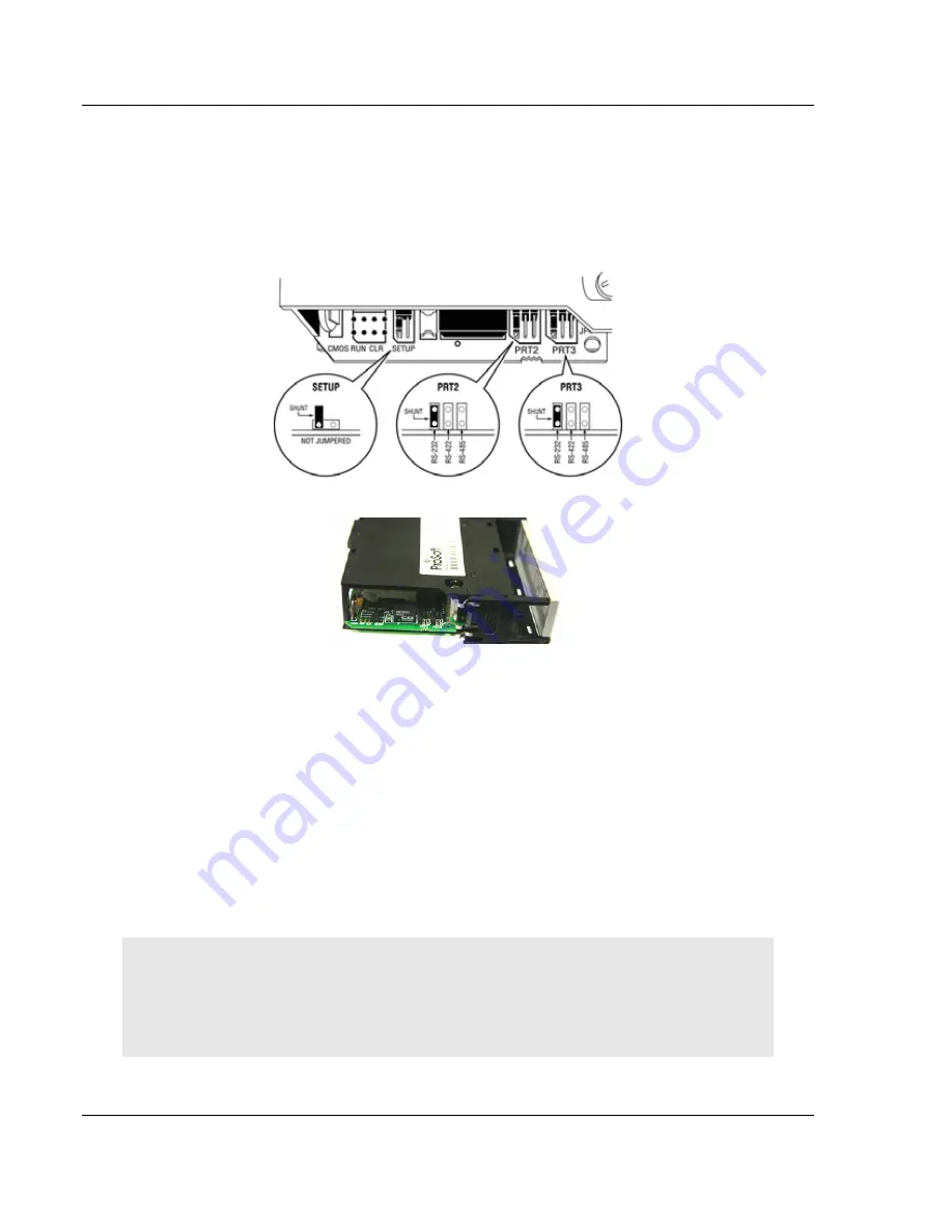
2.4 Setting
Jumpers
If you use an interface other than RS-232 (default), you must change the jumper
configuration to match the interface. There are three jumpers located at the
bottom of the module.
The following illustration shows the MVI56-MCM jumper configuration:
1
Set the PRT 2 (for application port 1) and PRT 3 (for application port 2)
jumpers for RS232, RS422 or RS485 to match the wiring needed for your
application. The default jumper setting for both application ports is RS-232.
2
The Setup Jumper acts as "write protection" for the module's flash memory.
In "write protected" mode, the Setup pins are not connected, and the
module's firmware cannot be overwritten. Do not jumper the Setup pins
together unless you are directed to do so by ProSoft Technical Support.
2.5
Install the Module in the Rack
If you have not already installed and configured your ControlLogix processor and
power supply, please do so before installing the MVI56-MCM module. Refer to
your Rockwell Automation product documentation for installation instructions.
Warning: You must follow all safety instructions when installing this or any other electronic
devices. Failure to follow safety procedures could result in damage to hardware or data, or even
serious injury or death to personnel. Refer to the documentation for each device you plan to
connect to verify that suitable safety procedures are in place before installing or servicing the
device.


