SECTION 3
Pronar T285/1
3.9
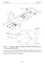
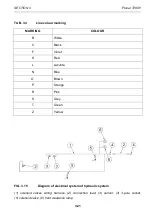
FIG. 3.5
Design and diagram of double line pneumatic braking system with
automatic braking force regulator
(1) air tank, (2) control valve, (3) braking force regulator, (4) pneumatic cylinder, (5) line
connector (yellow), (6) line connector (red), (7) air filter, (8) air tank control connector, (9)
relay valve, (10) socket (yellow), (11) socket (red)
The pneumatic brakes are activated from the tractor driver's cab by pressing on the brake
pedal. The function of the control valve (2) - figure (3.4) and (3.5) is the operation of the
trailer's brakes simultaneously when tractor's brakes are applied Furthermore, in case of an
Содержание T285/1
Страница 2: ......
Страница 6: ......
Страница 11: ...SECTION 1 BASIC INFORMATION ...
Страница 26: ...Pronar T285 1 SECTION 1 1 16 ...
Страница 27: ...SECTION 2 SAFETY ADVICE ...
Страница 42: ...Pronar T285 1 SECTION 2 2 16 ...
Страница 43: ...SECTION 3 DESIGN AND OPERATING PRINCIPLE ...
Страница 64: ...Pronar T285 1 SECTION 3 3 22 ...
Страница 65: ...SECTION 4 CORRECT USE ...
Страница 91: ...SECTION 5 MAINTENANCE ...
Страница 124: ...Pronar T285 1 SECTION 5 5 34 FIG 5 13 Trailer s lubrication points part 1 ...
Страница 125: ...SECTION 5 Pronar T285 1 5 35 FIG 5 14 Trailer s lubrication points part 2 ...
Страница 134: ...Pronar T285 1 SECTION 5 5 44 ...
Страница 135: ...NOTES ...
Страница 136: ......

