


Pronar T285/1
SECTION 3
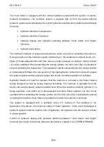
3.6
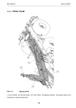
Complete tipping frame comprises rear frame (1) - figure 3.2, central frame (2) and hook
frame (3) to which is screwed the hook (6). Tipping frame is secured to lower frame with the
aid of tipping axle and tipping cylinder (4). Hook lock automatically falls or rises depending on
position of frame. Individual frames are connected with the aid of pins seated in sleeves.
Tipping frame lock mechanism (5) is secured to the left longitudinal member of the central
frame.
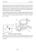
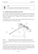
FIG. 3.3
Tipping frame locking
(1) left limit switch, (2) right limit switch, (3) switching cylinder, (4) bolt with nut, (5) clearance
light I, (6) clearance light II, (7) indicator plate
Содержание T285/1
Страница 2: ......
Страница 6: ......
Страница 11: ...SECTION 1 BASIC INFORMATION ...
Страница 26: ...Pronar T285 1 SECTION 1 1 16 ...
Страница 27: ...SECTION 2 SAFETY ADVICE ...
Страница 42: ...Pronar T285 1 SECTION 2 2 16 ...
Страница 43: ...SECTION 3 DESIGN AND OPERATING PRINCIPLE ...
Страница 64: ...Pronar T285 1 SECTION 3 3 22 ...
Страница 65: ...SECTION 4 CORRECT USE ...
Страница 91: ...SECTION 5 MAINTENANCE ...
Страница 124: ...Pronar T285 1 SECTION 5 5 34 FIG 5 13 Trailer s lubrication points part 1 ...
Страница 125: ...SECTION 5 Pronar T285 1 5 35 FIG 5 14 Trailer s lubrication points part 2 ...
Страница 134: ...Pronar T285 1 SECTION 5 5 44 ...
Страница 135: ...NOTES ...
Страница 136: ......


