Optional Units and Expansion Boards
PL-5700 Series User’s Manual
3-4
The DIM module can be inserted and removed up to 20 times. Repeated handling may
bend the clips on both edges of the module. Hold the module at an angle to the DIMM
socket to insert it.
Commercially available DIM modules may result in malfunction or failure of the PL,
if specifications differ from Digital’s DIM modules.
4. Refit the rear maintenance hatch, and tighten the screw.
<Removing the DIM module>
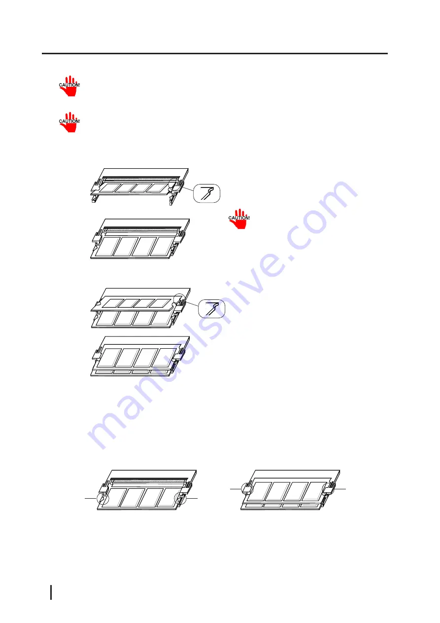
Carefully spread the clips on both edges of the DIM module, in the direction of the
arrows, to remove the module.
2. Hold the DIM module connector at an angle
to the DIMM socket, and insert the con-
nector into the socket
Be sure to hold the module at an angle
when inserting it.
3. Push the DIM module inward until the clips
on both ends lock.
2. Hold the DIM module connector at an angle
to the DIMM socket, and insert the con-
nector into the socket.
3. Push the DIM module inward until the clips
on both ends lock.
<Installing a module in BANK 1>
<Installing a module in BANK 0>
(NOTE: These figures show the PL-EM002)
Removing from BANK
0
Removing from BANK
1
^
^
^
^


