16
© 2014 Proceq SA
NOTE! For larger areas it is advisable not to set “Return to
start on new line” and to measure the lines alternatively start
to end, back from end to start.
• Position the probe cart at the first start line in a optimum position (the
MC
14
/
15
at the mid line of the rebars running parallel to the moving
direction, both rectangles in the probe symbol are green and of equal,
minimum size) and tap on reset
8
followed by tapping on
.
• Move the probe cart crosswise over the rebars. Above each rebar,
when the red LED of MC
14
/
15
lights up, you may measure the rebar
diameter and on completion, it will be displayed. If the spacing be-
tween the rebars is in the range of 5 to 13 cm (2.00 to 5.20 inch), set
the respective Neighboring Rebar Correction value first.
At the end of the first line a marker (dotted blue line) is set.
To proceed with the next line tap
10
or push
12
and
13
simultaneously on
the probe. The cursor jumps to the next measuring row, either to the start
line or remains at the end line, depending on whether “Return to start on
new line” is set or not.
Changing the cursor position works like in the Single-Line Mode. Addi-
tionally one can change to another line within the displayed area (which
also can be changed as described in ”3.4 Measurement Screen”). How-
ever, to delete the already scanned rebars of one line set the cursor to
the zero line and tap
. By tapping on
and
all measured
data of all lines would be deleted.
At the start of each line you may change the probe direction (e. g. when
measuring on a wall along the bottom line close to the slab).
• Tap on
.The arrow in the probe cart symbol changes from to
.
For the next line you may change back to
.
NOTE! By changing the setting “Line Height” during the
measurements the height of all lines including the ones al-
ready measured will change and hence, also the line posi-
tions. Change the line height only if it was previously wrongly
set.
At each rebar you may measure the rebar diameter. At the end, set one
common diameter, normally the smallest one (see “3.7 Practical Hints”).
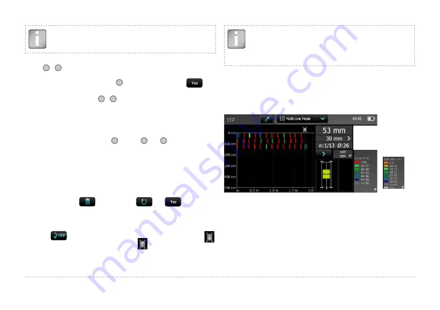
Figure 11 shows the rebars in a plan view in different colors depending on
the measured cover. Red means the cover is smaller than the minimum
set.
Rebars with insufficient cover in red, others have sufficient cover
Actual cover
Distance from MC to rebar
no. of snapshots/no. of rebars
/ last measured diameter
Alternatively
diameter ranges
cover ranges,
< xx in red
if minimum
cover set
Accurate probe
position if
rectangles green
and of same size
A rebar will only be shown up to 90 % of
the cover ranges indicated in Figure 2.
Figure 11:
Screen of Multi-Line Mode
Alternatively the diameter can be displayed in different colors by tapping
on the cover spectrum. Rebars of which the diameter was not measured
or set are shown in white. Diameters measured are shown in the respec-
tive color. Diameters set in the Single-Line View are shown additionally
with an orange cross bar in the middle of the rebar (see Figure 20).


