14
© 2014 Proceq SA
Single-Line Mode
PM-630
PM-650
NOTE! It is advisable to locate the first and second layer re-
bars with the Locating Mode to find the optimum line posi-
tion prior to measuring with the Single-Line Mode.
The Single-Line Mode is mainly used if cover must be shown along one
line on a rather long distance (e. g. in a tunnel). Therefore the measure-
ments are made across the first layer rebars.
The maximum scan length is 999 m / 3’280 feet in each direction (to the
right and to the left from the zero line).
• Enter the setting menu by tapping on
5
. Set the correct settings, es-
pecially Rebar Diameter, Unit, Minimum Cover and Display Curve.
In case Single-Line scanning is done over rebars of different diameters
and/or of different spacing measure each diameter.
• Position the probe cart at the start line in an optimum position (the MC
14
/
15
at the mid line of the rebars running parallel to the moving direc-
tion, both rectangles in the probe symbol are of equal minimum size).
• In case
is shown at
7
tap on it and
will be shown.
• Start with the measurement if the cursor is at the start line. If not per-
form a reset
8
.
• Move the probe cart with constant speed crosswise over the rebars,
not exceeding the maximum speed (speed bar half filled in green).
• Above each rebar, when the red LED of MC
14
/
15
lights up, you may
measure the rebar diameter and on completion, it will be displayed
in blue. The measured diameter may be deleted within 5 seconds by
tapping on
6
.
• In case the spacing between the rebars is in the range of 5 to 13 cm
(2.00 to 5.20 inch), set the respective Neighboring Rebar Correction
value first (see Figure 26).
The cursor position can be adapted in two ways to changed cart position:
• Tap on the cursor and wait until it becomes white and orange. Move
the cursor to the desired position (even left to the zero line is pos-
sible). Be aware: Scanning is not anymore possible between the new
cursor position and the zero-line. Already scanned rebars cannot be
removed by a new scanning but you may scan again on the left of
the first rebar or on the right of the last rebar. To delete the already
scanned rebars tap
and
.
• Tap on
and set the required displacement distance. In case you
must jump due to an obstacle like a column, move the cart until the
right wheels touch the column, set the displacement distance (column
width + 107 mm / 4.20 inch for the cart width) and reposition the cart
with the left wheels touching the column. Tap on
/
.
At the end when stopped scanning a marker (dotted blue line) is set.
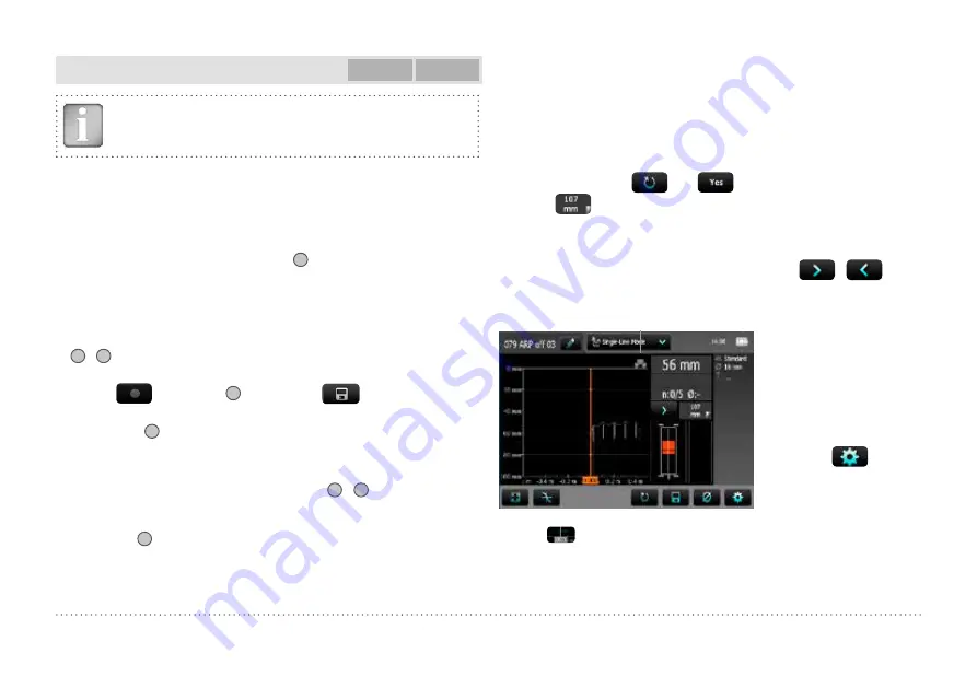
Probe
position
Red indicates rebars with insuf-
ficient cover, others with sufficient
cover.
Red dotted is the minimum
required cover. Blue number
indicates measured diameter.
Either the Cover, Signal Strength
or None curve can be displayed
by tapping on
and chang-
ing “Display Curve”.
To see the actual cursor position short tap on the cursor and the position is shown in white on
the X-axis.
The actual position is shown in a resolution of ± 3 mm / 0.12 inch.
The rebars are displayed to scale depending on the diameter
The cover curve is shown (if selected) within the cover ranges indicated in Figure 2 but a rebar
will only be shown up to 90 % of those limits.


