Other Features
116
NOTE
The indicator light on the control device
illuminates when power is supplied (when the
lift electrical circuit is activated by the switch
on the dashboard).
To stow the platform, detach the restraint belt
and fold the left handrail, then fold the right
handrail (lift the slam lock handles to fold
handrails). Re-fasten restraint belt. Press down
and hold the STOW button until the lift is fully
stowed.
THRESHOLD WARNING SYSTEM (TWS)
ADJUSTMENT
There are three verifications to perform; 1)
Adjust Aiming of Acoustic Sensor Beam, 2) Test
Aim of Acoustic Sensor Beam, and 3) Adjust
Acoustic Sensor Timing.
Adjustment of the sensor timing is done at the
factory and should not need to be repeated in
the field. Readjustment should only be
considered if the sensor aiming could not be
adjusted to ignore both the wheelchair in the
aisle and the platform during its normal
movement.
Adjust Aiming of Acoustic Sensor Beam
1. Place wheelchair with passenger in center
aisle of coach, pointed at doorway where
Threshold Warning System (TWS) is
installed. The TWS should not detect a
wheelchair and passenger when they are
located this far from doorway.
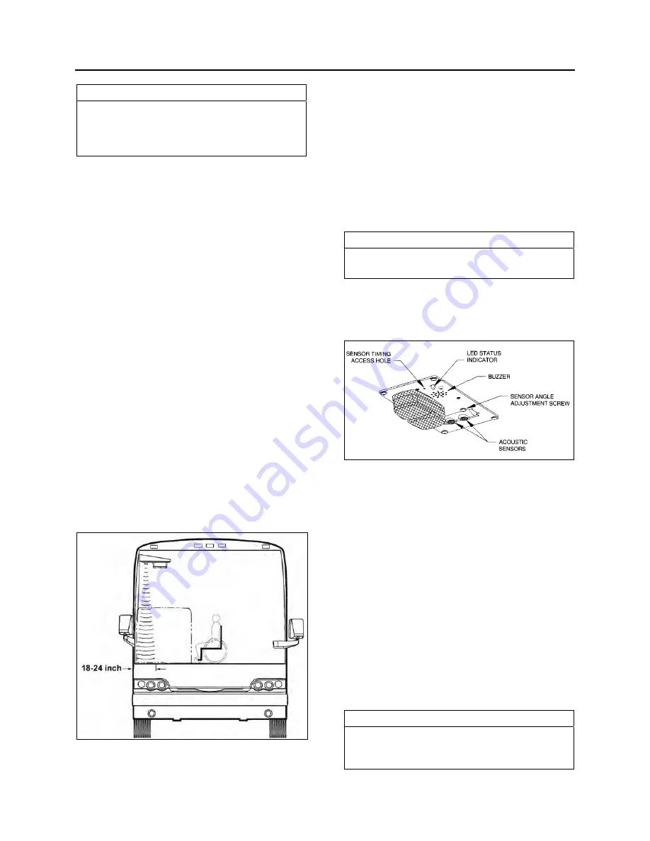
TWS AREA
23371
2. Turn power to lift on (LED on TWS module
will light steady) and indicator light on the
control device illuminates. If wheelchair and
passenger are detected by acoustic sensors
the LED will flash, the buzzer will sound and
the module red light will flash. If this occurs it
is necessary to adjust aiming of sensors.
3. Turn sensor angle adjustment screw
clockwise to move direction of beam away
from center aisle and towards doorway.
Stop adjustment when LED ceases to flash.
NOTE
Only in rare instances will adjustment be
needed in the counterclockwise direction.
4. Move centerline of small wheels of
wheelchair (with passenger) to within 24
inches of doorway and repeat aiming
procedure in previous step.
TWS MODULE DETAIL
23368
Test Aim of Acoustic Sensor Beam
1. Move wheelchair and passenger slowly
towards doorway. TWS should detect
wheelchair and passenger (LED will flash,
buzzer will sound and the module red light
will flash) when centerline of front wheels is
between 18 and 24 inches from doorway.
2. Open vehicle access door above lift. Lower
platform to ground and place wheelchair and
passenger at rear of platform. Rollstop (rear
barrier) should be up. Raise platform to floor
level. This normal platform motion with
wheelchair and passenger aboard should
not actuate TWS. If LED does flash (buzzer
will also sound and module red light will
flash), turn sensor adjustment screw slightly
counterclockwise.
NOTE
If an adjustment is made, repeat the previous
step where wheelchair is between 18 and 24
inches from doorway.
Содержание X3-45 2011
Страница 1: ...COACH MANUFACTURER OPERATOR S MANUAL X3 45 COACH PA1581...
Страница 4: ......
Страница 6: ......
Страница 7: ...Safety Precautions 1 SAFE OPERATING PRACTICES 2 DEFENSIVE DRIVING PRACTICES 2 OTHER PRECAUTIONS 3...
Страница 10: ......
Страница 24: ......
Страница 128: ......
Страница 134: ......
Страница 166: ...Care and Maintenance 160 COMPONENTS IDENTIFICATION COMPONENTS REPRESENTATION MAY DIFFER SLIGHTLY FROM AN ACTUAL VEHICLE...
Страница 171: ...Technical Information 165 X3 45 OVERALL DIMENSIONS SIDE ELEVATION 18673...
Страница 172: ...Technical Information 166 X3 45 OVERALL DIMENSIONS TOP FRONT AND REAR VIEWS 18674...
Страница 182: ......
Страница 186: ......
Страница 206: ......


