User Manual
ScanLog 96 Pen Drive Version
32
LOW / HIGH CLIPPING
APPENDIX B
For mA/mV/V inputs the measured PV is a scaled value between the set values for ‘PV Range Low’ and ‘PV Range High’
parameters corresponding to the Signal Minimum and Signal Maximum values respectively. Refer Appendix A.
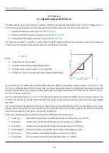
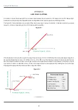
The Figure B.1 below illustrates an example of flow rate measurement using a transmitter / transducer producing a signal
range of 4 - 20 mA corresponding to 0.0 to 100.0 Liters per Minute (LPM).
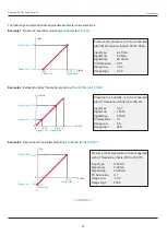
If this transmitter is to be used for a system having a flow rate range of 0.0 to 75.0 LPM then the actual useful signal range from
the example transmitter is 4 mA (~ 0.0 LPM) to 16 mA (~ 75.0 LPM) only. If no Clipping is applied on the measured flow rate
then the scaled PV will also include ‘out-of-range’ values for the signal values below 4 mA and above 16 mA (may be due to
open sensor condition or calibration errors). These out-of-range values can be suppressed by enabling the Low and/or High
Clippings with appropriate Clip values as shown in figure B.2 below.
Y
Transducer Signal (4 - 20 mA)
(0mA, -25.0)
(4mA, 0.0)
(20mA, 100.0)
Flow Rate (0 - 100.0 LPM)
X
Figure B.1
Figure B.2
Y
Transducer Signal (4 - 20 mA)
(0mA, 0.0)
(4mA, 0.0)
Scaled PV (0 - 100.0 LPM)
X
Low Clipping
(16mA, 75.0)
High Clipping
(20mA, 75.0)
PV Range Low
: 0.0
PV Range High
: 100.0
Enable Low Clipping
: Yes
Low Clip Value
: 0.0
Enable High Clipping
: Yes
High Clip Value
: 75.0
Parameter Values

