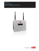
User Manual
ScanLog 96 Pen Drive Version
1
FRONT PANEL : LAYOUT AND OPERATION
Section 1
Figure 1.1
2 X 16 LCD Display
Keys
USB Connector
ScanLog 96
AL4
AL3
AL2
AL1
AUTO
Boiler Pressure
2.1 PSI
Upper Row
Lower Row
Alarm Status LEDs
Auto / Manual
Scan Mode Status
The front panel comprises of 2 X 16 (2 rows of 16 characters each) LCD Display, LED indicators & membrane keys. Refer
Figure 1.1 below.
LCD DISPLAY
The LCD Display has 2 rows, the Upper Row & the Lower Row; each having 16 Characters.
In normal mode of operation (Run Mode), the Upper Row displays the Channel Names and the Lower Row displays the
corresponding Process Values followed by Units. Refer Figure 1.2 (a) below.
Boiler Pressure
2.1 PSI
INPUT TYPE>>
Type K (Cr-Al)
Figure 1.2(a)
Figure 1.2(b)
In Set-up Mode, the Upper Row displays the parameter
Name
and the Lower Row displays the corresponding parameter
Value
. Refer Figure 1.2(b) above.
LED INDICATORS
There are 5 front panel 3mm round RED LED indicators described below in table 1.1.
Table 1.1
Remains off for Single Channel Version
In Dual Channel Version the ON status indicates that the
process value indication for channels is updated
automatically with user set Scan Time.
A
UTO
AL
1
Flashes while Alarm-1 of any one or more channels is active.
LED
Status
AL
2
AL
3
AL
4
Flashes while Alarm-2 of any one or more channels is active.
Flashes while Alarm-3 of any one or more channels is active.
Flashes while Alarm-4 of any one or more channels is active.


