20 - 80 kVA parallel UPS systems
User’s and Installation Manual
1018390
Revision C
37
7.5 Signal inputs
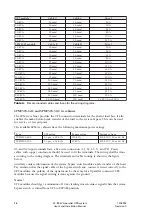
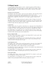
The programmable auxiliary inputs are used to control the operation of UPS modules. A
double shielded cable is the best alternative but single shielded twisted multipair cable is
also usable. Remember that signals should not have a galvanic connection to any mains
connected circuits.
Emergency Power Off (EPO)
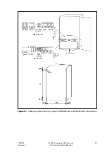
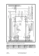
The emergency shut down wiring is connected to the terminal X4 with maximum resistance
of 10 ohm. It can also be used for a remote shut down in the event of a room
overtemperature by thermal relay. EPO terminals must not be connected in series with the
parallel system configuration. Internal EPO circuits require a galvanic isolation of the
signals.
The terminal X4 is a ‘normally closed’ type of connection. Hence, the logic circuitry will
immediately shut down the UPS module when the connection is open. The terminal X4 has
to be shorted to keep the UPS module running. A manual start is needed to make the UPS
module run again after the emergence power off mode.
Generator On
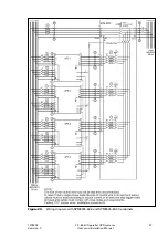
Auxiliary contact wires of a generator control device are connected to the terminal X219. It
is used for inhibiting the transfer to static bypass line when the UPS module is supplied from
an unstable AC source. The information has to be connected to all parallel UPS modules.
The terminal X219 is a ‘normally open’ type of connection. Hence the logic circuitry will
prevent the transfer to unstable power source when the connection is closed. UPS modules
are delivered the connection open on the terminal X219.
Remote Output On/Off
The remote output on/off wiring is connected to the terminal X220. It can be used to turn
off the UPS module output from a distance.
The terminal X220 is a ‘normally open’ type of connection. Hence the logic circuitry will
turn off the inverter when the connection is closed. In order to turn on the inverter the
connection between these pins has to be open.
System Bypass Switch
The auxiliary contact wiring of the system bypass switch is connected to the terminal X221.
The information has to be connected to all parallel UPS modules. Make sure that the
polarity of the auxiliary contact wiring is the same for all UPS modules.
In parallel UPS systems this signal must be connected to the auxiliary contact information of
the system bypass switch in the tie panel.
The terminal X221 is a ‘normally open’ type of connection. Hence the logic circuitry will
transfer the UPS modules to internal bypass line when the connection is closed.
Environment Alarm
The building alarm wiring is connected to the terminal X222. For example, it can be used
for overtemperature or smoke detector alarms.
The terminal X222 is a ‘normally open’ type of connection. Hence the logic circuitry will
indicate to the user through the RS-232 when the connection is closed.
Содержание 9305 HS Series
Страница 1: ...User s and Installation Manual 20 80 kVA parallel UPS systems...
Страница 2: ......

