20 - 80 kVA parallel UPS systems
User’s and Installation Manual
1018390
Revision C
35
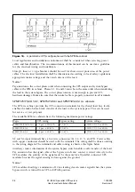
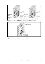
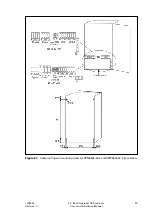
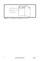
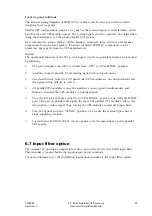
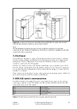
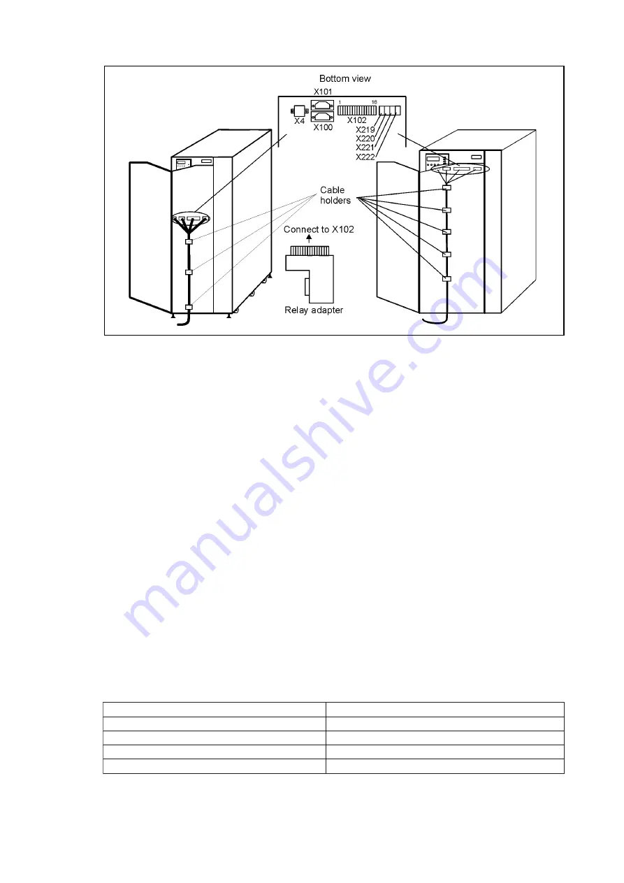
Figure 25.
Location of terminals in 20/30 kVA (left) and 40/50/60 kVA (right) UPS modules.
Cable holders should be used for routing to the terminals.
Note!
All communication connections must not have a galvanic connection to any mains
connected circuits. Reinforced insulation to the mains is required for equipment and cables
connected to these connections.
7.2 Software
UPS modules are designed to comply with LanSafe III and PowerVision software. Optional
software solution packages are delivered with communication devices for complete power
management. The pin configuration of the serial port should be verified if an unknown
software is connected to the UPS modules.
Software can control or monitor UPS modules individually, not as a parallel system. Check
from the software documentation that the platform running on your computer is supported.
Use no other than the communication cable provided with the package to connect the UPS
modules to a computer.
Please contact your local dealer if you are interested in special operating systems, SNMP and
more advanced power protection solution combinations.
7.3 RS-232 serial communication
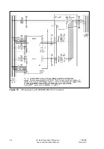
The RS232 interface on terminal X100 uses a 9-pin female D-sub connector. It is used for
connecting a computer to the UPS module. The data includes information about the utility,
load and the status of the UPS module.
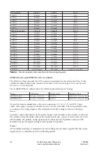
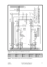
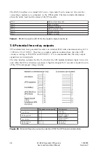
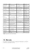
Table 7.
RS-232 connection (X100) for the computer, 9-pin female D-sub.
1
n
i
P
a
t
a
d
d
e
v
i
e
c
e
R
2
n
i
P
a
t
a
d
d
e
t
t
i
m
s
n
a
r
T
4
n
i
P
d
n
u
o
r
g
l
a
n
g
i
S
8
n
i
P
d
e
t
a
l
u
g
e
r
n
u
V
2
1
+
9
n
i
P
d
n
u
o
r
g
S
P
U
Содержание 9305 HS Series
Страница 1: ...User s and Installation Manual 20 80 kVA parallel UPS systems...
Страница 2: ......

