20 - 80 kVA parallel UPS systems
User’s and Installation Manual
1018390
Revision C
19
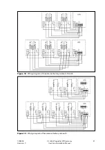
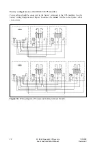
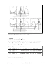
6.3 Input and output power cables
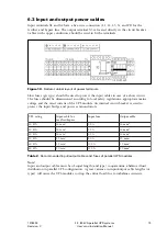
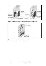
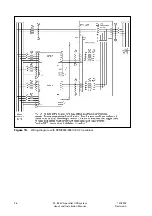
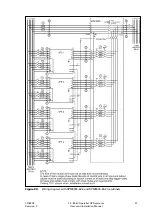
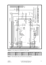
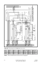
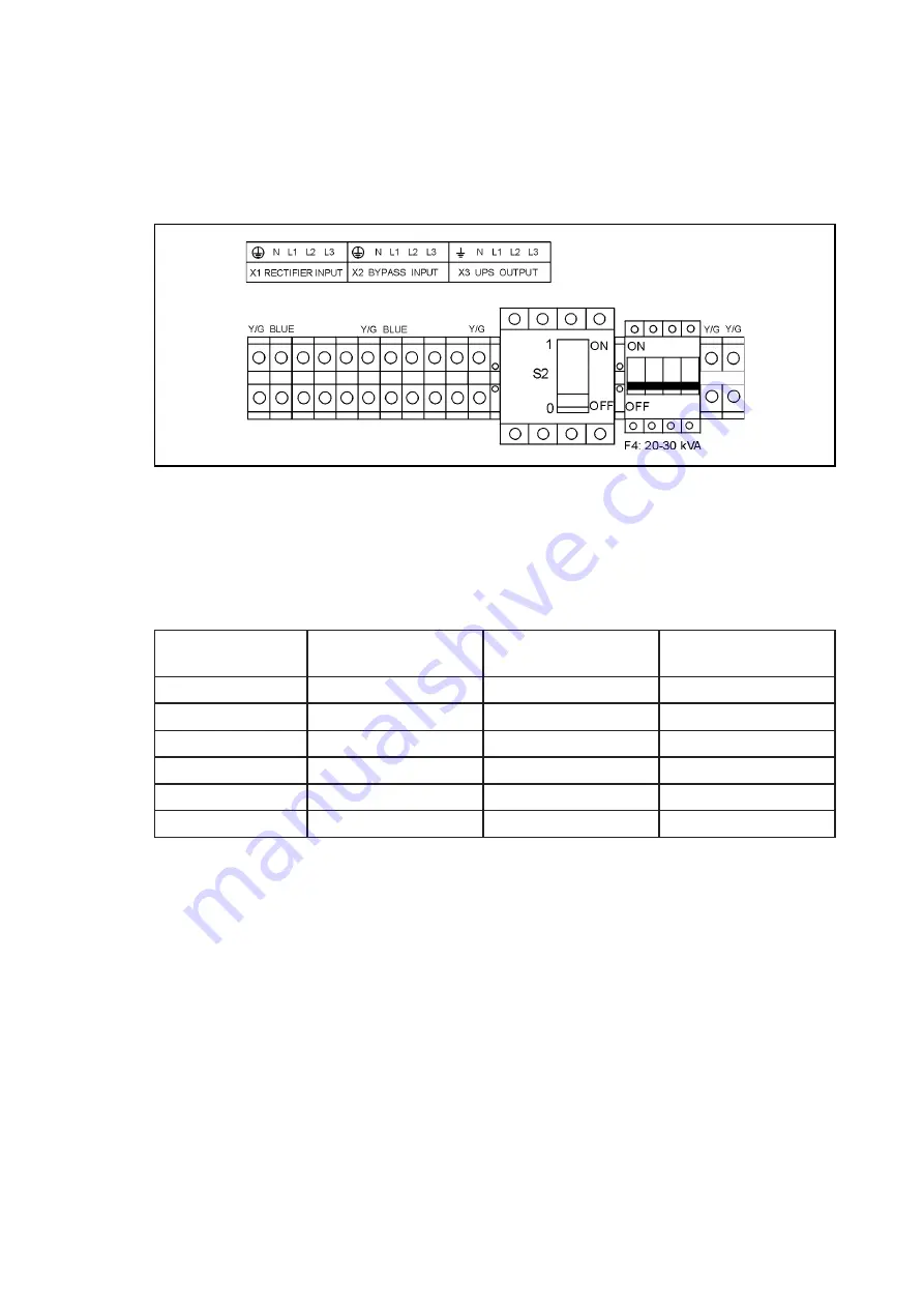
Input terminals X1 and X2 have a five-wire connection (L1, L2, L3, N, and PE) for the
rectifier and bypass line. The output terminal X3 is located directly in the circuit breaker.
Cables with copper conductors should be used to fit the terminals.
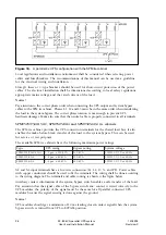
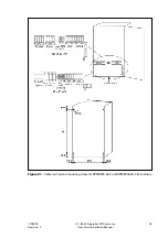
Figure 10.
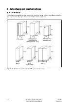
Bottom cabinet layout of power terminals.
Slow fuses (gG type) should be used to protect the input cables in case of a short circuit.
The fuses should be dimensioned according to local safety regulations, appropriate mains
voltage and the rated current of the UPS module. An internal circuit breaker is used to
protect the input bridge and power semiconductors.
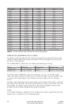
Table 2
. Recommended input/output cables and fuses of parallel UPS modules.
Note!
Input and output cables must be of equal length (and type) to quarantine a balanced load
distribution in parallel UPS configuration. A great variance in input/output cable lengths (or
types) will cause the UPS modules to drop the critical load due to imbalance currents.
g
n
i
t
a
r
S
P
U
r
o
f
e
l
b
a
c
t
u
p
n
I
s
s
a
p
y
b
/
r
e
i
f
i
t
c
e
r
e
s
u
f
t
u
p
n
I
e
l
b
a
c
t
u
p
t
u
O
A
V
k
0
2
²
m
m
6
1
A
0
5
6
1
m
m
2
A
V
k
0
3
²
m
m
6
1
A
0
5
6
1
m
m
2
A
V
k
0
4
²
m
m
6
1
A
3
6
6
1
m
m
2
A
V
k
0
5
²
m
m
5
2
A
0
8
5
2
m
m
2
A
V
k
0
6
²
m
m
5
3
A
0
0
1
5
3
m
m
2
A
V
k
0
8
²
m
m
0
5
A
5
2
1
0
5
m
m
2
Содержание 9305 HS Series
Страница 1: ...User s and Installation Manual 20 80 kVA parallel UPS systems...
Страница 2: ......

