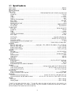
15
on the motor. Note that to get the best final finish,
however, the stock should be fed through the
machine so it will be sanded in line with the grain of
the wood on the final one or two passes.
9.0
Maintenance
Before doing maintenance on
the machine, disconnect it from the electrical
supply by pulling out the plug or switching off
the main switch. Failure to comply may cause
serious injury.
9.1
Cleaning and lubrication
For best results, make cleaning the sander a regular
shop procedure. Allowing excess build-up of dust
and debris can adversely affect performance
through loading of the abrasives, slippage on the
conveyor table, and/or the accumulation of material
inside the drums which can throw off the center of
balance.
Leave the dust collector on when cleaning dust from
the drums. Also brush the conveyor belt after
cleaning operations. If not cleaned, the conveyor
belt could allow stock to slip during sanding
operations.
NOTE: Bearings are pre-sealed and require no
lubrication.
•
Lubricate conveyor bushings as needed, and
check for wear.
•
Lubricate elevating leadscrew (A, Figure 18) as
needed.
•
Clean sawdust from abrasive strip and brush
dust from conveyor belt.
•
Keep gib areas clean (B, Figure 18).
Periodically lubricate gibs lightly with grease.
•
Blow dust from motors and switches. Blow dust
from inside of sanding drum, which may cause
vibration or offset the center of balance.
•
Check all set screws for tightness on parts such
as bearings, conveyor bed, and couplings.
Figure 18
9.2
Drum maintenance
The drum should not require removal from the
machine under normal circumstances. Should
maintenance ever become necessary, the drum has
been designed for easy removal and replacement.
Remove four socket head screws (C, Figure 19).
Carefully lift out drum with coupling (D) attached.
Figure 19
9.3
Conveyor belt replacement
1. Disconnect
sander
from
power.
2. Raise drum to highest position.
3. Loosen take-up screw nuts (Figure 11) on both
sides of conveyor to relieve belt tension, and
slide the driven roller fully inward.
4. Remove three (3) screws that attach conveyor
table to base. Lift up conveyor table and remove
it from machine. Avoid tearing the belt on any
edges underneath the conveyor bed.
Do not
allow the Trackers to drop, as they may break.
5. Install new belt along with trackers (see
sect.
11.0
), and re-install conveyor table. Tension
and track the new belt.
Note:
If the conveyor belt continually tracks to one
side of the machine, reversing the belt on the
conveyor bed may remedy the problem. To make
sure the conveyor bed is not twisted, place a level
on the conveyor bed. Level the machine if needed.
If there is still a problem, proceed with the steps
below:
Step 1
: Check conveyor drive roller and driven roller
to make sure they are parallel to surface of conveyor
bed. To do this, first center conveyor belt on the bed.
Then lay a straight-edge on the exposed edge of
conveyor bed on left (outboard) side, extending it
over the roller. Note distance between roller and
straightedge.
Step 2:
Now repeat Step 1 on right (inboard) side of
conveyor. Compare the measurements from side to
side. If they are not equal, loosen one of the
brackets that hold the roller in place. Tip this bracket
until distance between roller and straight-edge are
equal from side to side, then tighten bracket.
Содержание PM2244
Страница 20: ...20 14 1 1 PM2244 Head Assembly I Exploded View ...
Страница 21: ...21 14 1 2 PM2244 Head Assembly II Exploded View ...
Страница 22: ...22 14 1 3 PM2244 Head Assembly III Exploded View ...
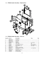
Страница 26: ...26 14 2 1 PM2244 Conveyor Bed Assembly Exploded View ...
Страница 29: ...29 15 0 Electrical Connections PM2244 Drum Sander ...
Страница 31: ...31 This page intentionally left blank ...
Страница 32: ...32 427 New Sanford Road LaVergne Tennessee 37086 Phone 800 274 6848 www powermatic com ...
Страница 52: ...20 14 1 1 Ensemble tête I de la ponceuse PM2244 Vue éclatée ...
Страница 53: ...21 14 1 2 Ensemble tête II de la ponceuse PM2244 Vue éclatée ...
Страница 54: ...22 14 1 3 Ensemble tête III de la ponceuse PM2244 Vue éclatée ...
Страница 58: ...26 14 2 1 Ensemble tapis du convoyeur PM2244 Vue éclatée ...
Страница 61: ...29 15 0 Branchements électriques Ponceuse à tambour PM2244 ...
Страница 63: ...31 La présente page a intentionnellement été laissée vierge ...
Страница 64: ...427 New Sanford Road La Vergne Tennessee 37086 États Unis Téléphone 1800 274 6848 www powermatic com ...
Страница 87: ...23 14 1 1 Conjunto de cabeza I de PM2244 Vista desarrollada ...
Страница 88: ...24 14 1 2 Conjunto de cabeza II de PM2244 Vista desarrollada ...
Страница 89: ...25 14 1 3 Conjunto de cabeza III de PM2244 Vista desarrollada ...
Страница 93: ...29 14 2 1 Conjunto de cabeza de lecho de banda transportadora de PM2244 Vista desarrollada ...
Страница 96: ...32 15 0 Conexiones eléctricas Lijadora de tambor PM2244 ...
Страница 98: ...34 ...
Страница 99: ...35 ...
Страница 100: ...36 427 New Sanford Road LaVergne Tennessee 37086 Teléfono 800 274 6848 www powermatic com ...


