12
8.0
Operations
Before using your drum sander, review the previous
sections on initial set-up and adjustment. Before
operating, make sure an abrasive strip is mounted
and a proper dust collection system is connected.
8.1
Basic Operating Procedure
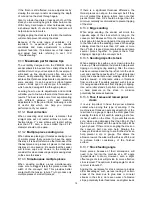
1. Establish depth of cut.
2. Start dust collection system.
3. Start sanding drum.
4. Start conveyor and select feed rate.
5. Feed stock through machine.
To feed stock through the sander, rest and hold
board to be sanded on conveyor belt, allowing
conveyor belt to carry board into drum. Once stock
is halfway through, reposition yourself to outfeed
side of machine to receive and control board as it
exits.
8.2
Controls and LED display
Figure 16 shows control panel functions.
Figure 16
A – Main power switch
B – Drum motor switch
C – Conveyor speed dial
D – Emergency stop (E-stop)
E – Unit selector
F – Zero depth reset
G – Conveyor speed indicator
H – Load indicator
I – Feed Logic ON indicator
J – Drum motor circle/ON indicator
K – Drum height
L – Drum height units
8.3
Drum motor operation
1. Connect power supply to machine. –
Display
remains dark.
2. Turn on main power switch (A). –
Display will
illuminate. Racetrack (G) may flash
continuously, indicating that emergency stop is
still engaged.
3. Rotate emergency stop (D) clockwise to
disengage stop.
4. Turn on drum motor by firmly pressing switch
(B) –
Illuminated circle (J) will run, and “ON” will
illuminate.
Note: If drum motor does not start, make sure
conveyor speed dial (C) is set to OFF.
5. Load indicator (H) may illuminate. –
When
motor is running without load, one bar may
illuminate. More bars are illuminated as load
increases.
6. Turn off drum motor switch (B). –
“ON” will go
dark. Circle (J) will continue running for 5
seconds while drum slows to a stop. Then circle
(J) will stop running.
Do not open drum hood
until drum comes to a complete stop.
8.4
Feed Logic activation
If load on the sanding drum becomes excessive and
motor is overloaded or exceeds specified current,
“FEED LOGIC” (I) flashes and “ON” (I) lights up.
Conveyor will be automatically slowed to highest
efficient speed.
8.5
Conveyor motor operation
Rotate conveyor speed dial (C, Figure 15) clockwise
to start and increase speed of conveyor. –
Racetrack (G) will illuminate and run. Conveyor
speed will show inside racetrack.
IMPORTANT:
If sander is shut off or E-stop is
engaged, conveyor speed dial must be returned to
OFF position in order to restart sander.
8.6
Unit conversion
Toggle unit selector button (E) to select imperial or
metric units. Units for drum height and conveyor
speed will change accordingly on the display. When
power is turned off, units default to imperial.
8.7
Drum height setting
Lower drum until it just contacts workpiece, then
push zero depth reset button (F, Figure 16) to zero
the setting of drum height from workpiece. The
handwheel is then used to lower the drum in exact
increments for each pass, by viewing the depth on
the control display (K).
Содержание PM2244
Страница 20: ...20 14 1 1 PM2244 Head Assembly I Exploded View ...
Страница 21: ...21 14 1 2 PM2244 Head Assembly II Exploded View ...
Страница 22: ...22 14 1 3 PM2244 Head Assembly III Exploded View ...
Страница 26: ...26 14 2 1 PM2244 Conveyor Bed Assembly Exploded View ...
Страница 29: ...29 15 0 Electrical Connections PM2244 Drum Sander ...
Страница 31: ...31 This page intentionally left blank ...
Страница 32: ...32 427 New Sanford Road LaVergne Tennessee 37086 Phone 800 274 6848 www powermatic com ...
Страница 52: ...20 14 1 1 Ensemble tête I de la ponceuse PM2244 Vue éclatée ...
Страница 53: ...21 14 1 2 Ensemble tête II de la ponceuse PM2244 Vue éclatée ...
Страница 54: ...22 14 1 3 Ensemble tête III de la ponceuse PM2244 Vue éclatée ...
Страница 58: ...26 14 2 1 Ensemble tapis du convoyeur PM2244 Vue éclatée ...
Страница 61: ...29 15 0 Branchements électriques Ponceuse à tambour PM2244 ...
Страница 63: ...31 La présente page a intentionnellement été laissée vierge ...
Страница 64: ...427 New Sanford Road La Vergne Tennessee 37086 États Unis Téléphone 1800 274 6848 www powermatic com ...
Страница 87: ...23 14 1 1 Conjunto de cabeza I de PM2244 Vista desarrollada ...
Страница 88: ...24 14 1 2 Conjunto de cabeza II de PM2244 Vista desarrollada ...
Страница 89: ...25 14 1 3 Conjunto de cabeza III de PM2244 Vista desarrollada ...
Страница 93: ...29 14 2 1 Conjunto de cabeza de lecho de banda transportadora de PM2244 Vista desarrollada ...
Страница 96: ...32 15 0 Conexiones eléctricas Lijadora de tambor PM2244 ...
Страница 98: ...34 ...
Страница 99: ...35 ...
Страница 100: ...36 427 New Sanford Road LaVergne Tennessee 37086 Teléfono 800 274 6848 www powermatic com ...


