


39
6-4-5
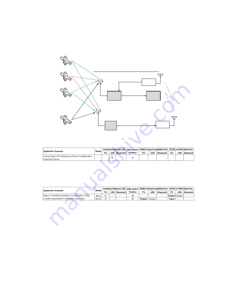
Real-Time Guidance Configuration Using Locally Setup Base/PC and Radio Connection
For line-of-sight real-time control application, telemetry radio can be used to send RTK base
data.
Base
USB/TTL mode / switch on A
TTL or Micro-USB
RTK
antenna
Telemetry
Radio
Telemetry
Radio
Rover
TTL mode / switch on B
RTK
antenna
Pin #2 of 6-pin
TTL connector
Setup for Real-Time Controller over Telemetry Radio
433MHz/915MHz/2.4GHz
Alpha RTK
Alpha
RTK
. . .
Real-Time
Controller
Pin #3 of 6-pin
TTL connector
Figure 6-20
Use section 6-2 method to configure one Alpha receiver into RTK rover. Depending on what’s available
to determine base antenna position, select one of the options to configure the second Alpha RTK
receiver into RTK base as described in section 6-3.
Assume the radio is properly setup for sending and receiving RTK base data at 115200 baud rate, (1)
connect RTK base UART output on pin-3 and GND on pin-6 of the 6-pin connector to radio transmitter,
(2) connect RTK rover UART input on pin-2 and GND on pin-6 of the 6-pin connector to radio receiver,
(3) connect RTK rover UART output on pin-3 of the 6-pin connector and GND on pin-4 of the 4-pin
connector to the real-time controller, apply power to both radios then RTK rover will be able to
receive RTK base data and function.