


AM2020/AFP1010 Troubleshooting Guide 50432 Revision A 8/13/97
15
If Relay Mapping is enabled (XPP switch 2=ON), it will
consume two address (place a two in the blank).
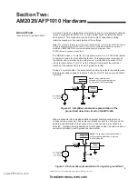
___
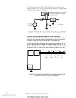
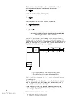
Depending on how each card is configured, the expander cards
of the Transponder (XPC, XPM, or XPR) can take up to 8 addresses.
If the card is an XPC-8 that is using all eight circuits (Style Y) and
is also configured for Canadian Dual Stage operation, it will
consume sixteen addresses. Calculate the number of
addresses that each card is consuming and enter the number
on the corresponding line.
First expander card
___
Second expander card
___
Third expander card
___
Total number of addresses consumed
___
Take the total number of addresses consumed (above) and add it to the base
address of the Transponder (set via the two rotary switches on the XPP-1)
subtract one, and this will give you the last address that is being taken by the
Transponder. Now that all the Transponder addresses are known, we may begin
troubleshooting the invalid reply.
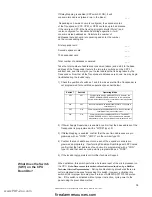
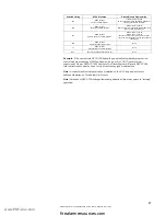
1) Check the position of switches 7 and 8 to make sure that the Transponder is
not programmed for Local Mode operation (see chart below).
2) If Power Supply Supervision is enabled, confirm that the base address of the
Transponder is programmed with a "MTRB" type I.D.
3) If Relay Mapping is enabled, confirm that the next two addresses are pro
grammed with an "FORC", "CMXC" or other similar type I.D.
4) Confirm that each address point on each of the expander cards is pro
grammed appropriately. If performing Canadian Dual Stage with XPC cards,
confirm that the first address of each circuit is programmed with a "CON"
type I.D. and that each second point is programmed as a "FORC".
5) If the invalid reply persists call Notifier Technical Support.
When activated, this switch performs a hardware reset of the microprocessor on
the CPU.
Note: Never press this switch unless instructed to do so by a Notifier
Technical Service Representative.
During troubleshooting procedures there are
certain diagnostic reasons for pressing this switch. However, activating this
switch at the improper time may result in loss of AM2020/AFP1010 fire protec-
tion. If this switch is activated without proper instruction, cycle power to the
panel using the prescribed method.
Switch 7
Switch 8
Operating Mode
OFF
OFF
Communicates with the AM2020/AFP1010. However, the
RESET, ACKNOWLEDGE, and ALL CALL commands are
ignored. Automatically reverts to Local Mode if communications
is lost.
ON
OFF
No communication with the AM2020/AFP1010. Functions in
Local Mode only.
OFF
ON
Communicates with the AM2020/AFP1010. Will not function in
Local Mode if communications is lost.
ON
ON
Communicates with the AM2020/AFP1010. The RESET,
ACKNOWLEDGE, and ALL CALL commands are accepted.
Automatically reverts to Local Mode if communications is lost.
What Does the Switch
(SW1) on the CPU
Board Do?
www.PDF-Zoo.com
firealarmresources.com
Содержание Notifier AFP1010
Страница 45: ...AM2020 AFP1010 Troubleshooting Guide 50432 Revision A 8 13 97 45 NOTES www PDF Zoo com firealarmresources com...
Страница 46: ...AM2020 AFP1010 Troubleshooting Guide 50432 Revision A 8 13 97 46 NOTES www PDF Zoo com firealarmresources com...
Страница 47: ...AM2020 AFP1010 Troubleshooting Guide 50432 Revision A 8 13 97 47 NOTES www PDF Zoo com firealarmresources com...


