

AM2020/AFP1010 Troubleshooting Guide 50432 Revision A 8/13/97
9
2) Disconnect the EIA-232 loop from the Serial Interface Board. Wait for one
minute. If the ground fault clears, reconnect this loop to the SIB but discon-
nect the wiring from the external equipment (CRTs, printers, etc.) that are
connected to this loop. If the ground fault clears, the problem lies with the
external equipment. If the ground fault remains, the problem is with the
actual field wiring.
3) Disconnect the EIA-485 loop from the Serial Interface Board. Wait for one
minute. If the ground fault clears, reconnect this wiring to the SIB but
disconnect the wiring at the external equipment (AMG, annunciators, etc.). If
the ground fault clears, the problem is with the external equipment (an RPT-
485W repeater module may be required to isolate the annunciator loop). If
the ground fault is still present, the problem is in the field wiring.
4) Disconnect all field wiring from any AVPS-24s, AA-30s, AA-120s, AMGs,
FFT-7s and any other equipment in the system which share a common
reference with the same battery that the MPS-24A is connected to.
a) If the system has multiple power supplies with ground fault circuitry, use
isolation devices (i.e., RPT-485, ACT-1, etc.) to remove the electrical
connection. When this is not possible, disable all but one ground fault
detection circuit and connect the battery negative terminals of all power
supplies. Isolation of supplies is preferable since multiple power supplies
with a single detection circuit result in increased capacitance to earth and
may give way to poor operation during an actual fault condition.
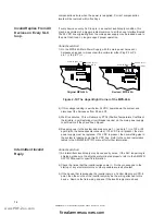
5) Disconnect all field wiring from terminal block TB3 on the MPS-24A.
6) Power down the panel. Disconnect the ribbon cable that connects the SIB
plug P4 to the DIA plug P4. Disconnect the ribbon cable that runs between
the CPU plug P3 to the DIA plug P3. Apply power to the panel. If the ground
fault condition has cleared, the source of the ground fault is on the Display
Interface Assembly (DIA) and it must be replaced. One simple check on the
DIA is to make sure that a gasket is in place between the LCD display and
the front of the metal assembly. If this gasket is missing, a temporary
solution is to use electrical tape to isolate the display.
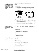
7) Disconnect the main power harnesses from the MPS-24A plugs P2 and P4.
8) Disconnect the 2-pin trouble cable from the CPU plug P2 (if connected).
9) Disconnect the battery connection at the batteries while leaving any common
connection intact. If the ground fault still exists, replace the MPS-24A.
Low Chamber Value.
Low Chamber Value is an indication that the detection means of an addressable
(Photoelectric, Ionization, and Thermal) detector may be failing. The trouble
condition is produced when the signal from the detector falls below 20% of the
alarm threshold.
Corrective Action:
1) Replace the addressable detector. To do this, remove the old detector. Wait
approximately three minutes and replace with the new detector. Allow several
minutes for the trouble to clear.
2) If the trouble persists, call Notifier Technical Support.
Maintenance Required is an indication that the detection chamber of an address-
able detector (Photoelectric and Ionization only) may be becoming increasingly
dirty. The trouble condition is produced when the level in the chamber climbs
Maintenance Required/
Pre-Alarm Alert.
www.PDF-Zoo.com
firealarmresources.com
Содержание Notifier AFP1010
Страница 45: ...AM2020 AFP1010 Troubleshooting Guide 50432 Revision A 8 13 97 45 NOTES www PDF Zoo com firealarmresources com...
Страница 46: ...AM2020 AFP1010 Troubleshooting Guide 50432 Revision A 8 13 97 46 NOTES www PDF Zoo com firealarmresources com...
Страница 47: ...AM2020 AFP1010 Troubleshooting Guide 50432 Revision A 8 13 97 47 NOTES www PDF Zoo com firealarmresources com...


