28
EN
ENGLISH
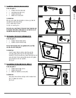
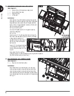
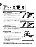
46. MOUNTING THE LID HANDLES
Part Required :
2 x Lid Handles
(#6)
4 x Large Handle Standoffs
(#7)
1 x Gas Lid
1 x Charcoal Lid
8 x M6x15 mm Screws
(#A)
Installation
:
• Attach 2 pcs Lid Handles and 4 pcs Large Handle
Standoffs to the Gas Lid and Charcoal Lid using 8 x
M6x15 mm Screws. See Fig. 46.1
Note: Slots on both side of Lid Handle must be
inserted into the embossed area on inside area of
Handle Standoffs. See Fig. 46.2.
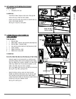
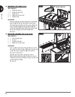
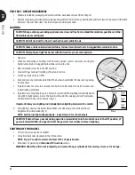
47. MOUNTING THE WIRE HOSE RETAINER
Part Required :
1 x Hose Wire Retainer
(pre-assembled on hose)
1 x Left Support Leg
(#44)
1 x M6x10 mm Screw
(#D)
Note: If there is no regulator included, ignore this step.
Installation
:
• Attach Hose Wire Retainer to the Left
(Front) Support Leg.
Use: 1 x M6x10 mm Screw. See Fig. 47.
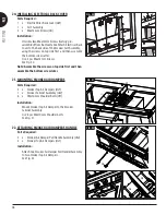
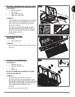
48. INSTALLING GAS SPARKER BATTERIES
Part Required :
1 x AA Battery
Installation
:
• Unscrew
(counter clockwise) Sparker Button from the
panel. Insert AA battery with the "+" end facing out
as per Fig. 48.
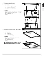
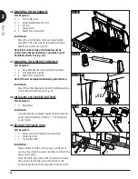
49. REPLACE THE POWER CORD
Part Required :
1 x Power Cord with Female Connector (#42)
1 x Cable Clip (#53)
1 x Cover Plate (#54)
Installation
:
• Please replace with the correct power cord for your
country, if you find the power cord does not match the
plug you are using.
• Place the cable clips on the correct power cord. Insert
the power cord into the grove at the back of the
bottom table. Secure the cable clip to the back of the
7.1
6
6
6
7.1
7.1
7.2
7.2
A
A
A
A
FIG. 46.1
FIG. 46.2
7.2
FIG. 47
HOSE
RETAINER
44
D
+
_
FIG. 48
FIG. 49
54
53
42
42


