AVH-P5200BT/XNUC
105
5
6
7
8
5
6
7
8
C
D
F
A
B
E
1
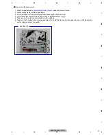
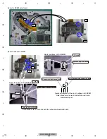
Adjustment procedure:
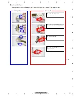
1. Turn back the DVD mechanism module to ensure pickup adjustment.
As turning back the module may result in the scratched disc, place a coin around 1.5mm thick on the desk,
and turn back and set the module so that the spot indicated in
1
comes directly above the coin.
2. Attach the pickup.
(See How to Remove the Pickup of the Mecha Unit.)
For the precautions in handling the pickup, see the Precautions in PU Handling below:
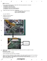
3. For the method
1
:
Refer to the connection diagram and connect the oscilloscope based on AGND2 so the RF signal can be monitored.
For the method
2
:
The device requires no setting. Skip to the fourth procedure.
4. Power ON the product and load the adjustment disc (GGV1018).
5. After setting the disc type to 1 DVD layer in the front-end test mode, power ON and move the pickup to the inner
circumference (CRG-Home).
6. LD
ON
7. Execute focus close, all automatic adjustment in the status and tracking close.
Further, execute all automatic adjustment in that status as well.
8. Search the middle circumference (ID: 100000) and take the pickup to the middle circumference.
9. For the method
1
:
Skip to the tenth procedure.
For the method
2
:
After Tracking Open first, execute all automatic adjustment and then tracking close with the command that can be
displayed in RF.
Further, execute all automatic adjustment in that status as well.
10. Using the torques (T2) driver,
For the method
1
:
Slightly screw the skew adjustment screw A while viewing the RF waveform level of the oscilloscope to maximize the level.
Slightly screw the skew adjustment screw B while the pickup stays in the middle circumference to maximize the level.
Slightly screw the skew adjustment screw A again while the pickup stays in the middle circumference to maximize the level.
(Perform adjustment in order of A => B => A, and finally rotate the screws clockwise to complete adjustment.)
For the method
2
:
Slightly screw the skew adjustment screw A while viewing the RF level value in the OSD display to maximize the level.
Slightly screw the skew adjustment screw B while the pickup stays in the middle circumference to maximize the level.
Slightly screw the skew adjustment screw A again while the pickup stays in the middle circumference to maximize the level.
(Perform adjustment in order of A => B => A, and finally rotate the screws clockwise to complete adjustment.)
11. Power OFF in the test mode, and check that the disc is stopped before ejecting.
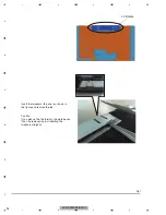
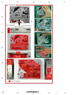
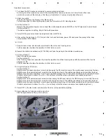
12. Apply adhesive for fixing skew and screw lock.
See the figure below for the spots to adhere.
Содержание Super Tuner IIID AVH-P5200BT
Страница 29: ...AVH P5200BT XNUC 29 5 6 7 8 5 6 7 8 C D F A B E ...
Страница 64: ...AVH P5200BT XNUC 64 1 2 3 4 1 2 3 4 C D F A B E ...
Страница 65: ...AVH P5200BT XNUC 65 5 6 7 8 5 6 7 8 C D F A B E ...
Страница 102: ...AVH P5200BT XNUC 102 1 2 3 4 1 2 3 4 C D F A B E ...
Страница 116: ...AVH P5200BT XNUC 116 1 2 3 4 1 2 3 4 C D F A B E 9 3 EXTERIOR 2 D E C B H G Drive Unit A A B C E D ...
Страница 157: ...AVH P5200BT XNUC 157 5 6 7 8 5 6 7 8 C D F A B E ...
Страница 161: ...AVH P5200BT XNUC 161 5 6 7 8 5 6 7 8 C D F A B E ...
Страница 171: ...AVH P5200BT XNUC 171 5 6 7 8 5 6 7 8 C D F A B E ...
Страница 172: ...AVH P5200BT XNUC 172 1 2 3 4 1 2 3 4 C D F A B E 10 14 DRIVE UNIT K K MAIN PCB UNIT CN2001 2 5 A ...
Страница 173: ...AVH P5200BT XNUC 173 5 6 7 8 5 6 7 8 C D F A B E M L K L SWITCH PCB UNIT M VOLUME PCB UNIT CXC6638 CXC6639 ...
Страница 187: ...AVH P5200BT XNUC 187 5 6 7 8 5 6 7 8 C D F A B E ...

