AVH-P5200BT/XNUC
92
1
2
3
4
1
2
3
4
C
D
F
A
B
E
1
2
Fig.
6
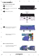
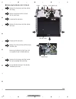
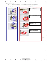
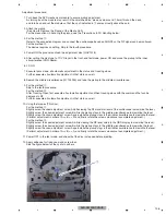
Remove
the
two
screws
and
then
remove
the
two
Guids(Right
side,
Left
side).
P
ull
out
the
M
onitor
Assy
in
the
direction
indicated
by
an
arrow.
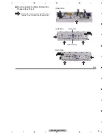
Remove
the
two
screws
and
then
remove
the
Spring.
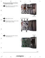
Remove
the
screw
and
then
remove
the
Arm
and
Cover.
Disconnect
the
connector.
Remove
the
five
screws
and
then
remove
the
Cover.
Disconnect
the
connector.
Remove
the
three
screws
and
then
remove
the
M
otor
Unit.
Removing
the
M
otor
Unit,
the
Drive
Unit
can
operate
to
lead
to
the
M
onitor
Assy.
1
2
3
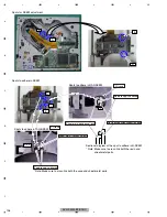
Removing
the
M
onitor
Unit
1
/
2
(Fig.
6
)
M
onitor
Assy
M
otor
Unit
Arm
and
Cover
3
Cover
1
Spring
4
4
4
4
4
4
5
6
7
8
5
6
6
6
7
7
8
Содержание Super Tuner IIID AVH-P5200BT
Страница 29: ...AVH P5200BT XNUC 29 5 6 7 8 5 6 7 8 C D F A B E ...
Страница 64: ...AVH P5200BT XNUC 64 1 2 3 4 1 2 3 4 C D F A B E ...
Страница 65: ...AVH P5200BT XNUC 65 5 6 7 8 5 6 7 8 C D F A B E ...
Страница 102: ...AVH P5200BT XNUC 102 1 2 3 4 1 2 3 4 C D F A B E ...
Страница 116: ...AVH P5200BT XNUC 116 1 2 3 4 1 2 3 4 C D F A B E 9 3 EXTERIOR 2 D E C B H G Drive Unit A A B C E D ...
Страница 157: ...AVH P5200BT XNUC 157 5 6 7 8 5 6 7 8 C D F A B E ...
Страница 161: ...AVH P5200BT XNUC 161 5 6 7 8 5 6 7 8 C D F A B E ...
Страница 171: ...AVH P5200BT XNUC 171 5 6 7 8 5 6 7 8 C D F A B E ...
Страница 172: ...AVH P5200BT XNUC 172 1 2 3 4 1 2 3 4 C D F A B E 10 14 DRIVE UNIT K K MAIN PCB UNIT CN2001 2 5 A ...
Страница 173: ...AVH P5200BT XNUC 173 5 6 7 8 5 6 7 8 C D F A B E M L K L SWITCH PCB UNIT M VOLUME PCB UNIT CXC6638 CXC6639 ...
Страница 187: ...AVH P5200BT XNUC 187 5 6 7 8 5 6 7 8 C D F A B E ...

