


AVH-P5200BT/XNUC
111
5
6
7
8
5
6
7
8
C
D
F
A
B
E
BACKLIGHT DRIVER
No
Adustment/Check Item
Input Point
Input signal
Measurement point
Check/Adjustment
Trigger
Control/Frequency
Note
1
B
AC
K
L
IGH
T
TP
:
P
WRB
L
D
C 8.0 V ± 0.2 V
TP
:
B
L
P
16.0 V ± 3 V
DIMPLS
O
p
erati
o
nal
frequency
: 200 Hz
DIMMER is adjusted by
the Duty.
Internal oscillatory frequency
:
381.
67
kH
z
External oscillatory frequency
:
476.
63
kH
z/524.
29
kH
z
(O
perati
o
nal
frequency range :
430 kH
z to
530 kH
z)
S
Y
N
C
IN
P
U
T DU
TY 90%
Internal oscillatory /External
frequency can be changed, when it
is operating.
PWR
B
L
, MBL
P
W,
BL
C
L
K,
D
IMPL
S
conforms to the hardware
specifications.
2
BLERR
TP
:
BLERR1
0.981 V to 2.642 V
DIMPLS
(Duty 100%)
-
An output voltage range in product
normal operation
REGULATOR
No
Adustment/Check Item
Input Point
Input signal
Measurement point
Check/Adjustment
Trigger
Note
1
PNLVI
TP : PWRVI
DC5.1 V ± 0.2 V
TP
:
P
N
LVI
3.4 V ± 0.2 V
MONPW
TP : MONPW + 3.0 V to + 3.3 V
2
GD33V
TP : PWRVI
DC5.1 V ± 0.2 V
TP
:
GD33V
3.4 V ± 0.2 V
MONPW
TP : MONPW + 3.0 V to + 3.3 V
3
GD12V
TP : PWRVI
DC5.1 V ± 0.2 V
TP
:
GD12V
1.2 V ± 0.1 V
MONPW
(GD33V)
TP : MONPW + 3.0 V to + 3.3 V
COMPOSITE SIGNAL
No
Adustment/Check Item
Input Point
Input signal
Measurement point
Check/Adjustment
Trigger
Note
1
composite
TP : MOVBS
composite signal
1.0 Vp-p ± 1%(at white 100%)
-
Display confirmation
-
Please do not input the signal when
you don't turn on the power supply.
Check signal : Color bar, 10step
ANALOG-RGB SIGNAL
No
Adustment/Check Item
Input Point
Input signal
Measurement point
Check/Adjustment
Trigger
Note
TP : CSYNC
csync si
gnal
H
I
L
evel
2.
5 V mo
re than 3.
3 V
less than
LOW Level 1.5 V less than
TP : ANAG
TP
:
ANAB
TP
:
ANAR
1.1 Vp-p at + 2.4 V offset signal
1
Please do not input the signal when
you don't turn on the power supply.
-
analog-RGB
-
Display confirmation
A timing signal from the GERDA to the LCD module may destroy the built-in driver IC of the LCD module depending on its timing.
Please pay attention if you are going to control the GERDA directly with jigs.
When executing the display test mode with the UART etc., conform to the product movement for the time from the power on to
the reset cancellation/communication start, etc.
TP
:
P
W
RB
L
D
C 8.0 V ± 0.2 V
Содержание Super Tuner IIID AVH-P5200BT
Страница 29: ...AVH P5200BT XNUC 29 5 6 7 8 5 6 7 8 C D F A B E ...
Страница 64: ...AVH P5200BT XNUC 64 1 2 3 4 1 2 3 4 C D F A B E ...
Страница 65: ...AVH P5200BT XNUC 65 5 6 7 8 5 6 7 8 C D F A B E ...
Страница 102: ...AVH P5200BT XNUC 102 1 2 3 4 1 2 3 4 C D F A B E ...
Страница 116: ...AVH P5200BT XNUC 116 1 2 3 4 1 2 3 4 C D F A B E 9 3 EXTERIOR 2 D E C B H G Drive Unit A A B C E D ...
Страница 157: ...AVH P5200BT XNUC 157 5 6 7 8 5 6 7 8 C D F A B E ...
Страница 161: ...AVH P5200BT XNUC 161 5 6 7 8 5 6 7 8 C D F A B E ...
Страница 171: ...AVH P5200BT XNUC 171 5 6 7 8 5 6 7 8 C D F A B E ...
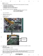
Страница 172: ...AVH P5200BT XNUC 172 1 2 3 4 1 2 3 4 C D F A B E 10 14 DRIVE UNIT K K MAIN PCB UNIT CN2001 2 5 A ...
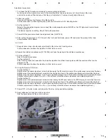
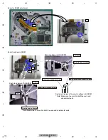
Страница 173: ...AVH P5200BT XNUC 173 5 6 7 8 5 6 7 8 C D F A B E M L K L SWITCH PCB UNIT M VOLUME PCB UNIT CXC6638 CXC6639 ...
Страница 187: ...AVH P5200BT XNUC 187 5 6 7 8 5 6 7 8 C D F A B E ...


